
This "Road Tunnels Manual" comprises 4 parts. The first part, Strategy and General Design, considers the strategic and design aspects and comprises the following chapters.
The chapter on Strategic Issues presents the principal strategic elements which any decision maker must take into account before making a decision concerning the selection or design of a tunnel. This chapter is particularly aimed at the decision-makers and tunnel designers of countries that are starting to tackle the construction or major refurbishment of a tunnel.
Tunnels, initially aimed at crossing an obstacle (in general a mountain), have become increasingly complex during recent years, incorporating increasingly complex equipment (including ventilation systems) and methods of operation. Such operation includes the deployment of control and supervision systems that enable the handling of vast amounts of data, and which can accommodate increasingly sophisticated management scenarios.

Figure 1: St Gotthard tunnel fire
Following the catastrophes in the Mont Blanc, Tauern and Gotthard (Figure 1) tunnels in the years 1999 and 2001, the need to adopt a holistic approach to tunnel safety was recognized. This resulted in stricter provisions from the tunnel design stage onwards, which have an important impact on specific civil engineering and tunnel equipment requirements.
In general, tunnels are considered as "expensive and risky" works, both with regard to their construction as well as their operation. This "image" makes some countries very reluctant to embark upon the construction of their first or railway tunnels. In order to address such concerns, increasing importance is being given to risk management (including construction and operation costs), accident or fire mitigation during operation and the optimisation of the tunnel facilities at the design, construction and operation stages. This risk and cost management is reinforced through current procurement and financing models for the construction of tunnels, which are increasingly being implemented as "Concession", "Design and Build" or "Private Public Partnership" models.
The chapter entitled Strategic Issues aims to:
This chapter is not designed to be a detailed handbook of the actions required by tunnel owners, or to specify the technical provisions to be implemented by designers, or to determine the tasks to be undertaken by operators to ensure a safe and comfortable tunnel environment. In particular, this chapter does not aim to be a design handbook. Its main objective is to make the reader aware of certain issues, in order to facilitate comprehension of this complex field, to raise awareness of the many possible errors in tunnel operations, and to have a better understanding of optimisation possibilities.
The page entitled Tunnel: a complex system, explains why a tunnel constitutes a "complex system" and lists the main interfaces between Civil Engineering, Ventilation and Safety aspects;
The page Steps of tunnel life analyses the various stages of a tunnel’s life cycle and underlines the key actions of each of these phases;
The page General design of the tunnel (new tunnel) presents the major elements which have to be considered when designing a new tunnel;
The page Renovation - Upgrading of existing tunnels concerns the upgrading and the refurbishment of existing tunnels under operation;
The page Costs of construction - Operation - Upgrading - Financial aspects explains issues relating to construction, operation and renovation costs, as well as the main issues specific to the modes of financing;
The page Complex underground road networks highlights the special features of complex underground and interconnected structures and provides case studies of complex tunnels via numerous monographs.
The page Regulations - Recommendations gives a list of the main recommendations, directives and regulations published by various countries in Europe and elsewhere in the world.
A tunnel constitutes a "complex system" which is the result of the interaction of very many parameters. These parameters can be gathered by subsets, the principal ones of which are represented in the diagram below (fig. 1).
All these parameters are variable and interactive, within each subset, and between the subsets themselves.
The relative weighting of the parameters and their character varies according to the nature of each tunnel. For example:
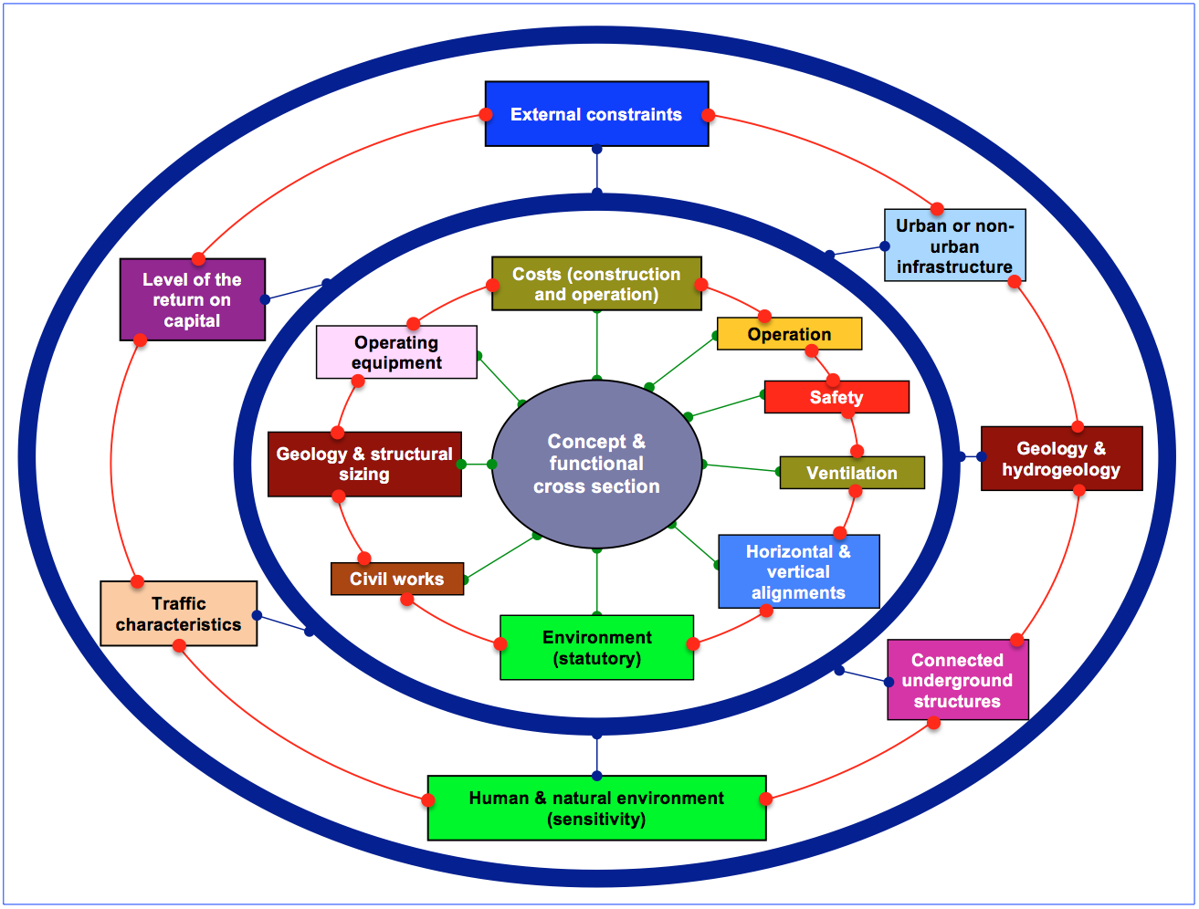
Fig. 1 : Diagram of main subsets of the "complex tunnel system"
Note 1: the links are multiple and often reversible - the general concept of the tunnel and the functional section are placed in the centre of the figure. Similar diagrams could be drawn up while placing other factors in the centre of the figure.
Note 2 : the first circle represents "technical fields". Some fields represent multiple aspects:
Note 3: the second circle represents the "context" in which the project is to be developed. Some elements represent multiple aspects:
The design of a new tunnel (or the refurbishment and upgrading of an old tunnel) requires these numerous parameters to be taken into account. The decision tree relating to these parameters is complex, and requires the input of experienced multidisciplinary parties. They must intervene as early as possible, for the following reasons:
Each tunnel is unique and a specific analysis has to be developed, while taking into account all the specific and particular conditions. This analysis is essential to bring suitable answers and to allow:
There is no "magic key solution", and a simple "copy and paste" process is almost always unsuitable.
The design and optimisation of a tunnel require:
Several examples are given below showing how it is possible to clarify the complexity, the interactivity, as well as the iterative and "circular" character of the analysis.
These examples are not exhaustive. Their aim is simply to make the reader aware of the issues and make it possible to focus considerations on each specific tunnel.
Table 1 below gives an example of the principal parameters concerning the aspects relating to civil engineering:
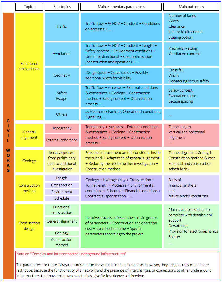
The first column of the table indicates the principal sets of parameters,
The interactions between parameters are numerous and often connected by circular links taking into account the overlaps between the various parameters.
The example below (Table 2) relates to the interactions between ventilation, the cross section, and safety:
TABLE 2 : INTERACTIONS BETWEEN PARAMETERS
The table reveals a certain number of parameters common to several columns (see line connectors), which create circular interactions between the various subsets of parameters.
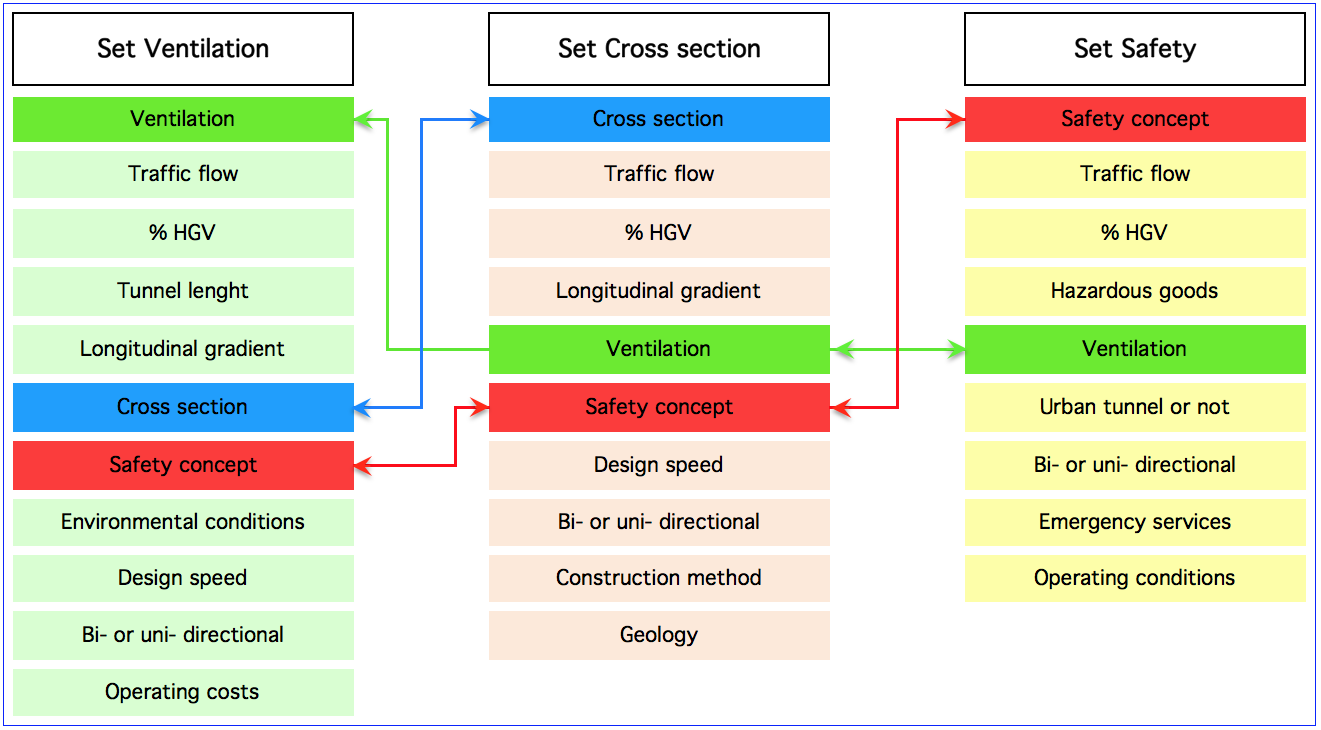
These interactions are linked by complex functions, which make a purely mathematical resolution of the problem nearly impossible. The resolution of the problem requires the definition of a hierarchy between the various parameters, followed by taking into account assumptions for the parameters of higher hierarchy. This hierarchy differs from one project to another, such as for example:
The process of resolution is then iterative and based on a first set of assumptions, as the previous examples show. This process requires a large transverse multi-technical experience of the engineers, making it possible to take into account the relevant parameters for the project, to better target the successive iterations, and to guarantee the best optimisation of the project, with the required level of service and safety.
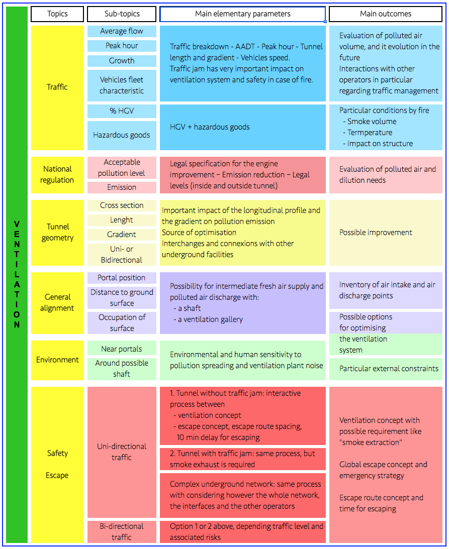
Table 3 below gives an example of the principal parameters concerning the aspects relating to ventilation. This table is not exhaustive.
As for "civil engineering", the interactions between parameters are numerous. They also are subject to circular relations.
The process to solve the problems is similar to the one outlined above for "civil engineering".
Table 3 : Main parameters influencing ventilation
4. Subset "Operation equipment"
They do not constitute fundamental parameters for the definition of the functional section, with the exception of:
"Operation equipment" constitutes on the other hand essential parameters for the dimensioning of the technical buildings at the portals, of underground mechanical and electrical sub-stations, and of all underground technical spaces, or various provisions, recesses and niches. They often require particular arrangements concerning temperature, air conditioning, and air quality.
They also are important parameters in terms of cost: construction, operation and maintenance.
"Operation equipment" constitutes essential parameters regarding tunnel safety. It must be designed, built and maintained in this objective:
The statistics available in many countries show, quite generally, that the rate of tunnel accidents is notoriously lower than that for the road network in the open air.
Apart from disasters, almost all the accidents recorded and documented in tunnels are mainly due to the following causes:
Safety aspects are to be broken down into:
Note: Additional information on tunnel accidents is available by following hyperlinks:
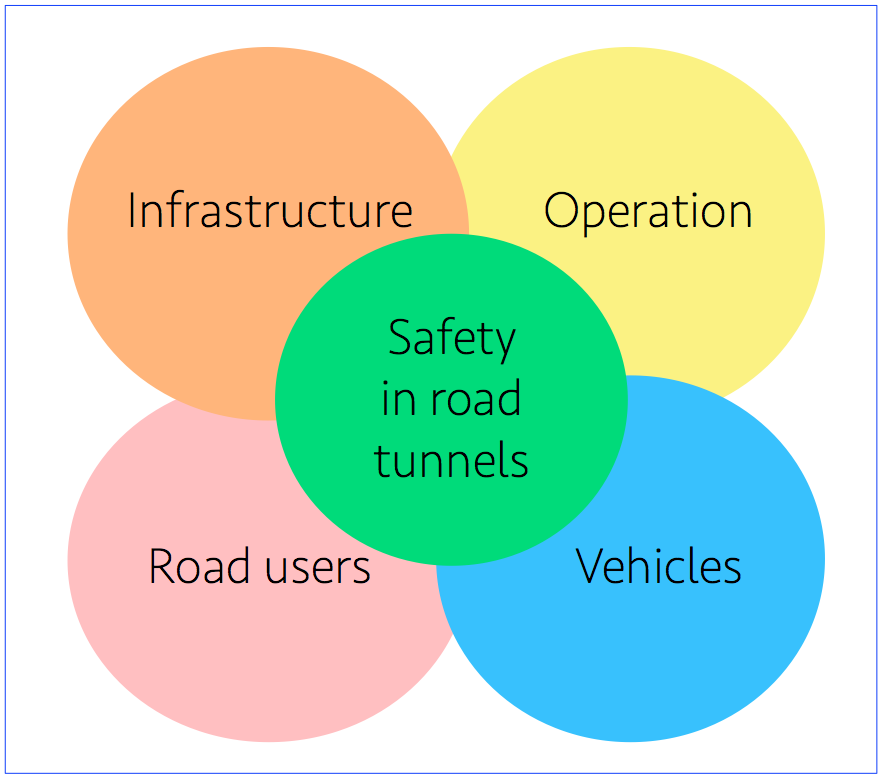
Fig. 2 : Factors affecting safety
The infrastructure is an essential parameter concerning the safety inside the tunnel (preventative and curative provisions), as well as the construction cost. However, one can invest highly in infrastructure without improving conditions of safety if essential provisions are not considered in parallel concerning:
These parameters relating to safety may affect in a more or less important way a tunnel project. The tables below give some examples.
Note: The four tables below refer to the four principal fields represented in Fig. 2.
| INFRASTRUCTURE | IMPACT | COMMENTS |
|---|---|---|
|
Visibility – Legibility – Exit and merging conditions on the interchanges and connections with other underground infrastructures |
|
Horizontal and vertical alignment - Coordination layout/vertical profile - Design of the interchanges and connections - Design of the ramps - Exit and merging areas |
|
Escape route |
|
Inside the tunnel - Parallel gallery - Direct external access - Connection between two tubes |
|
Emergency team accesses |
|
From the other tube - Dedicated access - Common with escape route |
|
Volume of people to escape |
|
Size of escape route - Spacing of the connections to the tunnel |
|
Ventilation |
|
Ventilation concept - Inadequacy of pure longitudinal system under certain operating and traffic conditions |
| OPERATION | IMPACT | COMMENTS |
|---|---|---|
|
Response plan procedure |
|
Signalling - SCADA - Communication with the users |
|
Intervention rescue team |
|
Size of the portal building - Eventual underground facilities - Specific tool - Size of water tanks |
|
Team training |
|
Particular external facilities - Special software |
| VEHICLES | IMPACT | COMMENTS |
|---|---|---|
|
Traffic flow average and peak hour |
|
Number of lanes - Ventilation concept and sizing |
|
Transport of dangerous goods |
|
Ventilation impact - Particular drainage for hazardous goods spillage - Operating procedures with particular convoy with fire brigade accompanying --> parking facilities and staff |
|
State of the vehicle |
|
In particular condition, size control and overheat control before entering --> gantry heat control + parking + staff |
|
Restriction of particular vehicle categories |
|
Example: urban tunnel dedicated to light vehicles - Tunnel size, ventilation escape routes |
| ROAD USERS | IMPACT | COMMENTS |
|---|---|---|
|
Information |
|
Leaflet distributed before entering - TV information campaign |
|
"Live" communication |
|
Signalling, VMS, radio broadcast, traffic lights, impact on cross section, mechanical and electrical equipment, SCADA, sometimes remote barriers |
|
Teaching |
|
Driving school (in several European countries) |
|
Guidance to escape routes |
|
Signalling - Handrail - Flash - Noise - Impact on mechanical and electrical equipment and SCADA |
|
Speed and spacing between vehicles control |
|
Radar and spacing detectors - Impact on mechanical and electrical equipment and SCADA |
A tunnel is a "complex system" which means in particular that:
Partial treatment of problems is unfortunately still rather frequent, due to lack of sufficient "tunnel culture" of the various actors involved in the design.
Control of this complex system is difficult but essential in order to:
In a parallel way the control of this complex system very often contributes to the technical and economical optimisation of the project, by a clear and early definition of the functions to be ensured and by using a value engineering process.
Taking into account, from the start of the project, the major issues relative to:
constitutes an effective approach to solving this complex equation.
The definition of the “tunnel function", as well as the "preliminary risks and dangers analysis" are often neglected or superficially treated. They are, however, an essential and indispensable "tool" for the technical, economical and safe optimization of a tunnel.
The " preliminary risks and dangers analysis " should not be confined to tunnel fires and constructive and operational provisions to minimize risks. It must also consider (which is rarely the case) the daily safety conditions to reduce the likelihood of incidents and their severity. This implies an analysis of the horizontal and vertical alignments, of the geometry of the ramps of the underground connections, of the visibility, of the likelihood of traffic congestion. This analysis must be done during the design of the alignment, while it is then still possible to improve the project in order to reduce the risk of incidents.
The key items to consider during each stage of the tunnel life are presented below.
This is the most important stage of the life of a new tunnel. It is has significant influence on construction and operation costs, safety, as well as management of the technical and financial risks.
This stage requires a transverse integration of all interfaces of the “complex system" that constitutes a tunnel. This integration has to start from the earliest stage of the design.
Experience testifies to the fact that this is unfortunately rarely the case and that often the design of a tunnel results from a succession of stages considered as independent. We note that :
With regard to civil engineering, the most important aspect is the management of technical risks (in particular geological) and of all the resulting consequences concerning construction costs and duration.
Considerations relating to risk management for construction have to be taken into account from the design stage. These considerations must be detailed and shared with the owner of the tunnel. Decisions concerning the risks must be developed and clearly documented.
The decision to take some risks does not necessarily constitute a mistake and must not necessarily be forbidden. For example working to a tight schedule does not allow the implementation of all the investigations that would be required to eliminate all uncertainties.
However, the decision to take a risk must result from a very detailed and soundly argued consideration of:
Taking a risk must not be the result of carelessness or incompetence of the various parties.
With regard to operational facilities, the reader’s attention is drawn to:
This stage of the "tunnel life" is often under-estimated and taken into account tardily. It requires taking time that is not often granted, and leads to the commissioning of the tunnel under unsatisfactory conditions, or even under conditions that highly expose safety risks.
This stage includes:
The main mission is to ensure:
It is also necessary to be able to step back and look objectively at daily routines in order to:
This page relates to the design of new tunnels. The design concerning the refurbishment and the safety upgrading of tunnels under operation is presented in page Renovation - Upgrading of existing tunnels.
The design of the horizontal and vertical alignment of a road or highway section, which includes a tunnel, constitutes a major and fundamental first stage in the creation of a new tunnel, to which the necessary attention is seldom given.
The consideration of the "complex system" which constitutes a tunnel has to start at the early stage of the design of the general alignment, which is seldom the case. It is however at this stage that technical and financial optimisations are the most important.
It is essential to mobilise from the earliest stage of the design a multidisciplinary team made up of very experienced specialists and designers, who will be able to identify all the project's potential problems, despite inevitably incomplete preliminary information. This team will be able to make good and reliable decisions for the major choices, and then consolidate these elements progressively taking into account the availability of additional information.
The objective of this section is not to define the rules regarding tunnel layout design (several countries' design handbooks are referred to in page Regulations - Recommendations) but essentially to sensitise the owners and the designers to the necessity of a global and multicultural approach, from the early stages of the design, and to the importance of essential experience that is paramount to the success of the project.
The definition of the horizontal and the vertical alignments and of the geometry of the underground interchanges or connections (in particular exit or merging areas) are an important stage in road safety. Many accidents are due to design faults as outlined in section 5.1 of page “Tunnel: a complex system” above.
The "Preliminary risk and Hazard analysis” should cover all aspects relating to geometry, legibility, visibility and the presence of any underground connections (see also section 6 of page “Tunnel: a complex system” above).
1.1. Countries without "tunnel culture"
In these countries owners and designers have a certain apprehension about tunnels. They very often prefer "acrobatic road layouts" passing along ridges, with steep gradients, huge retaining walls or very long viaducts, and sometimes tremendous consolidation works (which are very expensive and not always effective over a long period of time), in order to cross zones with active landslides.
Numerous examples of projects including tunnels and alignment variations designed with a global “system” approach demonstrate, in comparison with approaches refusing systematically the construction of tunnels:
The assistance of an external assessor makes it possible to mitigate the insufficiency or the lack of "tunnel culture", and to improve the project significantly.
The concept of a "complex system" is seldom integrated upstream, to the detriment of the global optimisation of the project. Too often the "geometry" of the new infrastructure is fixed by layout specialists without any integration of the whole set of constraints and tunnel components.
It is however essential to take into account from this stage all the parameters and interfaces described in page "Tunnel: a complex system" above, and in particular:
The functional transverse profile constitutes the second major stage of the design of a tunnel after selecting the alignment. As for the first stage, the "complex system" approach must be taken into account in a very attentive way, as upstream as possible with an experienced multidisciplinary team. All of the parameters and interfaces described in page Tunnel: a complex system must be considered.
This second stage (functional transverse profile) is not independent of the first stage (alignment), and it must obviously take into account the resulting provisions. The two stages are interdependent and very closely linked together.
Moreover, as mentioned in section 2.2 above, the process of the first two stages is iterative and interactive. There is no direct mathematical approach to bring a single response to the "complex system" analysis. There is also no uniqueness of answer but a very limited number of good answers and a great number of bad answers. The experience of the multidisciplinary team is essential for a good solution to be identified quickly.
The examples quoted in section 1 above illustrate that the provisions of the "functional transverse profile" can have a major impact on the design of the horizontal and vertical alignments.
Experience shows that the analysis of the "functional transverse profile" is very often incomplete and limited to the sole provisions of civil engineering, which leads inevitably to:
The major parameters of the "functional transverse profile" are as follows:
Safety must be a permanent concern to the contracting authority, the designers and the operators.
Safety must be considered from the early stage of the preliminary studies, using tools adapted to each of the design stages, of the tenders, of the preparation for the operation, and then during the operation period.
In a very schematic way:
The "Risk and hazard analysis" provisions, as well as the "Emergency response plan" are specified in the Book Safety.
3.2. General provisions
PIARC's recommendations are numerous in the fields of safety and operation for the finalisation of safety studies, the organisation of operation and emergencies, as well as the provisions for operation. The reader is invited to refer to theme : see book Safety.
This present chapter primarily treats safety and operation interfaces within the "complex system". The tables of section 5.2 of page "Tunnel: a complex system" indicate the degree of interdependence of each parameter compared to the various subsets of the project.
A certain number of parameters have a major impact from the upstream stages of the project onward. They must be analysed from the first phases of the design and deal in particular with:
These major parameters for the design of the tunnel are also the essential factors of the "hazard analysis", and drafts of the "intervention plan of the emergency teams". This is why we consider that it is essential that a "preliminary risk analysis", associated with a preliminary analysis of an "emergency response plan" should be carried out in the initial stages of the preliminary design. This analysis makes it possible to better describe the specific features of the tunnel and the functional and safety specifications which it must satisfy. It also contributes to a value engineering analysis, to a better design and to the technical and financial improvement and optimisation.
These parameters and their impacts are detailed in the following paragraphs
These parameters have an impact mainly on the functional cross-sectional profile (see section 2), and through it a partial impact on the layout:
Another fundamental traffic parameter is often neglected or deliberately evaded when designing a tunnel. It concerns the traffic congestion and the formation of "traffic jams" in tunnel. This parameter is particularly sensitive for tunnels which incorporate ramps and underground connections.
To postulate, as is often the case, that traffic management provisions will be taken to avoid the formation of "traffic jam" is fallacious and unrealistic as shown by the daily reality in urban areas. These provisions further lead to drastically reducing the volume of traffic entering the tunnel, reducing the capacity of the route and degrading the function and economic profitability of the infrastructure.
In most cases, this severe neglect inevitably leads to increased exposure of users to an unacceptable level of risk and danger.
The presence of "traffic jam" has significant impact on:
3.4. Evacuation of the users - access of the emergency teams
This is a fundamental parameter concerning the functional provisions and the general design. This parameter also often affects the alignment (direct exits to outside) and construction provisions: cross-passages - under gallery - parallel gallery - shelters or temporary refuges connected to a gallery.
Its analysis requires an integrated approach with the ventilation design (in particular the ventilation in case of fire), volume of traffic, risk analysis, drafting of the emergency response plan (in particular investigation of the scenarios ventilation / intervention) and construction methods.
It is necessary from a functional point of view to define the routes, their geometrical characteristics and spacing in order to ensure the flow of able-bodied and disabled people.
It is essential to insure the homogeneity, the legibility and the welcoming and calming character of these facilities. They are used by people in situations of stress (accident - fire), at the self-rescue stage (before the arrival of the emergency services). Their use has to offer a natural, simple, efficient and calming character in order to avoid the transformation of the state of stress into a state of panic.
Ventilation facilities designed as a pure "longitudinal ventilation" system have little impact on the "functional cross section" or on the "alignment".
This is not the case for "longitudinal ventilation" facilities equipped with a smoke extraction duct, or for "transverse ventilation" systems, "semi-transverse" or "semi-longitudinal" systems, "mixed" systems, or for ventilation systems including shafts or intermediate galleries permitting to draw or to discharge air outside other than at the tunnel portals. All these facilities have a very important impact on the "functional cross section", the "alignment" and all the additional underground structures.
The ventilation facilities of the traffic space are essentially designed in order to :
The ventilation facilities may also provide additional functions:
The ventilation facilities do not only concern the traffic space. They also concern:
The ventilation facilities have to be designed in order to be able to:
Communication with users has an important impact on the "functional transverse profile" through signalling.
The other major impacts do not relate to the whole of the "complex system". They relate to the subsystem concerning the operating equipment, in particular remote monitoring, detection, communications, traffic management, control and supervision, as well as the organisation of evacuation.
The operation of a tunnel and the intervention of the maintenance teams may require particular arrangements in order to enable interventions under full safety conditions, and to reduce restrictions to the traffic.
These arrangements concern for example the provision of lay-bys in front of the underground facilities requiring regular maintenance interventions, accessibility to materials for their replacement and maintenance (in particular heavy or cumbersome material).
The objective of this section is not to describe in detail operation facilities and equipment, their function or their design. These elements are defined in the recommendations of the current "Road Tunnels Manual", as well as in the handbooks or national recommendations listed in page "Regulations - Recommendations" hereafter.
The objective is to draw the attention of owners and designers to the particular issues peculiar to the equipment and the facilities of tunnel operation.
The operating equipment must allow the tunnel to fill its function, which is to ensure the passage of traffic, and to satisfy the double mission of providing for the users a good level of comfort and safety when crossing the tunnel.
The operation facilities must be suited to the function of the tunnel, its geographical location, its intrinsic features, the nature of the traffic, the infrastructures downstream and upstream of the tunnel, the major issues relating to safety and to emergency organisation, as well as the regulation and the cultural and socioeconomic environment of the country in which the tunnel is situated.
A plethora of operation facilities does not automatically contribute to the improvement of the level of service, comfort and safety of a tunnel. It requires increased maintenance and human intervention, which, if not implemented, may lead to a reduction in the reliability of the tunnel and its level of safety. The juxtaposition or the abuse of gadgets is also useless. The facilities must be suited, complementary, sometimes redundant (for the essential functions of safety), and have to form a coherent whole.
The facilities of operation are "living":
All these considerations lead to strategic choices of which the main ones are:
4.2.a. Energy - sources of power - electric distribution
For the tunnel equipment to function there must be a power sources. Large tunnels can require a power of several MW (megawatts), which may not always be available on site. Particular arrangements must be taken from the first stages of the design in order to strengthen and make more reliable the existing networks, or often to create new networks. The power supply is essential for the operation of the tunnel. It is also essential for its construction.
The supply of electric energy and its distribution inside the tunnel must provide:
Every tunnel is specific and has to be subjected to a specific analysis according to its geographical position, the context of the existing electrical networks, the energy supply conditions (priority or not priority), the possibility of increasing or not the power and the reliability of the existing public networks, the risks peculiar to the tunnel, as well as the conditions of intervention of the emergency services.
The facilities must be then designed consequently, and the operating procedures must be implemented according to the reliability of the system and the choices that have been taken during the design period.
The objectives concerning safety, in case of a power supply cut are:
The arrangements usually implemented for the electrical power supply are as follows:
4.2.b. Ventilation
PIARC recommendations are numerous in this field and constitute the essential international references for the conception and the design of ventilation facilities. In addition to the above, the reader should refer to the chapter on Ventilation concepts.
However, it must be remembered that even if the ventilation equipment constitutes one of the essential facilities in assuring the health, comfort and safety of the users in a tunnel, it is only one of the links of the system, in which the users, the operators and the emergency and rescue teams constitute the most important elements by their behaviour, their expertise and their capacity to act.
The ventilation facilities alone cannot deal with all scenarios, nor satisfy all the functions that might be assumed, especially concerning air cleaning and the protection of the environment.
The relevance of the choice of a ventilation system and its dimensioning requires lengthy experience, the understanding of the complex phenomena of fluid mechanics in an enclosed environment, associated with the successive stages of the development of a fire, the propagation, radiation and thermal exchanges, as well as the development and the propagation of toxic gases and smoke.
The ventilation facilities are in general energy-consuming and particular attention must be paid to the optimisation of their dimensioning and their operation, by using for example expert systems.
The ventilation facilities may be very complex, and their relevant management in case of fire may require the implementation of automated systems that allow to manage and master the situation more efficiently than an operator under stress.
As indicated in section 3.4 above, the ventilation facilities must above all satisfy the requirements for health and hygiene during normal conditions of operation, and to the objectives of safety in case of fire.
Hardiness, reliability, adaptability, longevity and optimisation of energy consumption constitute major quality criteria that the ventilation facilities must satisfy.
4.2.c. Additional equipment to the ventilation facilities
Two types of additional equipment for ventilation are often the subject of pressing demands from stakeholders, resident associations or lobbies:
A. Air cleaning facilities.
Page Tunnel impact on outside air quality deals with this question and the reader is invited to refer to it.
The implementation of air cleaning facilities is a recurrent demand of resident protection associations in urban areas. These facilities, usually installed underground, are very expensive to construct as well as to operate and maintain. They are also high consumers of energy.
Results to date are far from convincing, due in particular to important emission reductions from the vehicles, and to the difficulty for these systems to clean the very low concentrations of pollutants that are in the tunnel, contained in large volumes of air. Consequently, many systems installed in the last ten years are no longer operational.
The future of air cleaning facilities is very uncertain in countries where there is more coercive regulation, imposing more and more rigorous reductions of polluting emissions at the source.
B. Fixed fire suppression system (FFSS).
Page Fixed Fire Suppression Systems deals with this issue, and the reader is invited to refer to it.
The technologies are numerous and answer to varied criteria: fire fighting - containment of the fire - reduction of thermal radiation and temperature for the users situated in the vicinity of the fire - preservation of the tunnel structure against damage due to high temperature, etc.
These systems, even though presenting positive aspects, also present negative aspects related in particular to the deterioration of the conditions of visibility if they are activated from the start of the fire. The use of an FFSS requires a coherent approach to all aspects of the users' safety, as well as to ventilation and evacuation strategy.
The decision concerning the implementation or not of such systems is complex and has important consequences. It must be subject to a thorough reflection relating to the particular conditions of safety of the work concerned and to the added value obtained by the implementation of the system. It should not be taken under the influence of fashion or a lobby.
The FFSS requires the implementation of important maintenance measures, the carrying out of regular and frequent tests, without which its reliability cannot be assured.
4.2.d. Lighting
The recommendations of the CIE (International Commission for Lighting) have been criticised by PIARC because of the high levels of lighting to which they often lead. The reader is invited to refer to the technical report published by the CEN (European Committee of Standardization) that presents several methods including the CIE's.
Lighting is a fundamental tool to ensure the comfort and safety of the users in a tunnel. The objectives of the lighting level must be adapted to the geographical location of the tunnel (urban or not), its features (short or very long), to the volume and nature of the traffic.
Lighting equipment consumes a lot of power and developments are in progress to optimise their features and performance.
4.2.e. Data transmission - Supervision - SCADA
SCADA is the "nervous system" and the "brain" of the tunnel, permitting the compilation, transmission and treatment of information, and then the transmission of the equipment's operating instructions.
This system requires a meticulous analysis according to the specific conditions inside the tunnel, its facilities, the organisation and the mode of operation, the context of risks in which the tunnel is placed, as well as the arrangements and procedures implemented for interventions.
The organisation of the supervision and control centre has to be analysed very carefully, according to the specific context of the tunnel (or of the group of tunnels), the necessary human and material means, the missions to be assumed, the essential aid brought by the automatic devices or the expert systems to the operators in event of an incident, allowing the operators to reduce and simplify their tasks and to make them more efficient.
The detailed design of these systems is long, delicate and requires a very rigorous methodology of developing, of controlling by successive stages (in particular during factory tests), of testing, of globally controlling after integration of all the systems on site. Experience shows that the numerous errors noted on these systems come from the following gaps:
Page Supervisory Control And Data Acquisition systems (SCADA) of the manual sums up these different aspects.
4.2.f. Radio-communications - low voltage circuits
These facilities include:
4.2.g. Signalling
Signalling refers to page Evacuation route signs.
Even more than for the other facilities, an overabundance of signalling is detrimental to its relevance and objectives.
The legibility, the consistency, the homogeneity and the hierarchy of signalling (priority to evacuation signalling and information for users) have to be a priority of the signalling design inside the tunnel and on its approaches.
Fixed signage panels, traffic lanes signals, variable messages signals, traffic lights and stopping lights, signalling to emergency exits, the specific signalling of these exits, signalling of safety niches, physical devices for closing the lanes (removable barriers),horizontal markings and horizontal rumble strips are all part of the signalling devices. They assure a part of the communication with the users.
4.2.h. Devices for fire fighting
The devices for fire detection are either localised (detection of fire in the underground substations or the technical rooms), or linear (thermal sensing cable) inside the traffic space.
There are various devices for fire fighting:
4.2.i. Miscellaneous equipment
Other equipment may be installed according to the objectives and needs concerning safety, comfort and protection of the structure. Some examples are:
The upgrading (in particular for safety improvement) and refurbishment of existing tunnels in operation gives rise to specific problems of analysis and method. The degree of freedom is less than for new tunnels, because it is necessary to take into account the existing space and constraints. The technologies peculiar to each type of equipment and their integration are however identical.
The renovation and upgrading of a tunnel under operation quite often result in an increase of the construction schedule and costs, in much lower safety conditions during the works, and with badly controlled impacts on the traffic volume and conditions. These disadvantages are often the result of an incomplete analysis of the existing situation, the real condition of the tunnel, its facilities and its environment, as well as of a lack of strategy and procedures that would mitigate the effects on the traffic.
The page on Assessing and improving safety in existing tunnels proposes a methodology for the safety diagnosis of existing tunnels and the development of an upgrading programme. In addition, the page on Operation during maintenance and refurbishment works presents specific issues related to works carried out on tunnels in operation. Their dispositions help mitigate the problems mentioned above.
It is appropriate to draw the reader's attention to the key points of the following sections.
Detailed and rigorous diagnosis of a tunnel is an essential stage in the process of its upgrading or renovation. Unfortunately this stage is often neglected.
The physical diagnosis of a tunnel is required in order to:
This physical diagnosis must be supplemented by a diagnosis concerning the organisation, maintenance and operation procedures, as well as by a specific diagnosis concerning all documents relating to the organisation of safety and rescue interventions. This stage of diagnosis may eventually lead to the setting up of actions for the training of the various intervention parties in order to improve the global conditions of safety of the tunnel in its initial state prior to renovation.
The diagnosis must be followed by a risk analysis of the tunnel based on its actual state. This analysis has a double objective:
The diagnosis has to identify (without running the risk of late discoveries during the works period) if the existing facilities, supposedly in working condition, can be modified, be added to or integrated in the future updated facilities (technological compatibility - performance in particular for data collection and transmission, automatic functioning devices and SCADA).
The renovation or upgrading programme proceeds from two stages.
The development of the programme results from:
Depending on the physical environment of the tunnel and the spaces available, the optimum upgrading programme for the infrastructure or equipment may not be feasible under acceptable conditions, and that it is necessary to define a more restricted programme. This restricted programme may require the implementation of mitigating measures ensuring that the required level of safety is achieved in a global sense, after completion of the works.
The validation of the programme requires:
The upgrading or improvement programme does not necessarily require physical works. It may only require modification of the functions of the tunnel, or of the operating arrangements, for example:
The stage of design implementation and construction involves translating the renovation or upgrading programme into technical and contractual specifications and implementing it.
This stage requires a very detailed analysis of:
Tunnels are relatively expensive civil engineering structures with respect to their construction and operation. Particular attention must be paid from the beginning of the project in order to spot any possible technical and financial optimisations.
It is recommended from the first stages of the design to implement a process including:
This process will enable the optimisation of the project (construction and operation costs) and an improved management of the technical and financial risks, as well as the schedule.
The construction costs of tunnels are very variable and it is impossible to give representative ratios of costs per kilometre, because these ratios may vary in important proportions (average of 1 to 5) according in particular to:
At most it is possible to indicate that the average cost of a usual tunnel, built under average geotechnical conditions is about ten times the cost of the equivalent infrastructure built in open air (outside of urban areas).
The construction cost of a tunnel may be broken down into three types of cost:
The two diagrams below show examples of the breakdown of construction costs, on the one hand for tunnels for which the conditions of the civil engineering works are not complex, and on the other hand for tunnels for which the conditions of the civil engineering works are less favourable.
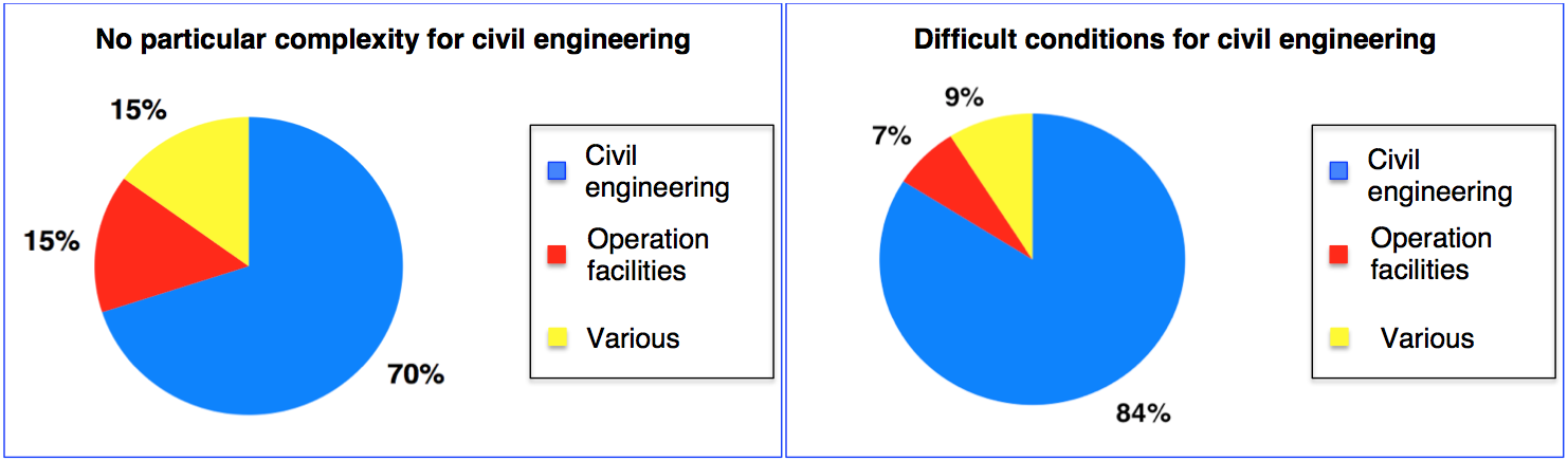
Fig. 1: Breakdown of construction costs
Note: these two diagrams show how important the costs are of the civil works and illustrate the consequences of an almost doubling the costs of civil works (-hand diagram).
The operation costs of a tunnel may be broken down into three types of cost:
The two diagrams below represent examples of breakdown (with constant economic conditions) of the construction costs (civil works, operation facilities, various costs) and of the global operation costs (accumulated over a duration of thirty years after the start of the operation period).

Fig. 2: Breakdown of the costs during a 30-year period
Note: these diagrams show how important the operation and maintenance costs are and how it is necessary to choose from the first stages of the tunnel design the arrangements that enable the optimisation of the recurrent operation and maintenance costs.
This section concerns the renovation or upgrading works that are required for “upgrading” to new regulations. The works concern the arrangements for evacuation, the resistance of the structure to fire, the operation and safety facilities, and all the requirements to satisfy the new safety regulations.
It is not possible to give statistical prices due to the diversity of existing tunnels, their condition, their traffic and the more or less important requirements of new safety regulations that may vary from one country to another.
The observations made in France for this nature of upgrading works for complying with the new regulations, which have been carried out since the year 2000, show a large variation of the corresponding budgets with a range of costs between about ten million Euros and several hundred million Euros (there have been several upgrading programmes with a budget of more than 200 million Euros).
Tunnels constitute costly infrastructure in terms of construction and operation, but this is offset by economic benefits including regional development, traffic fluidity, comfort, safety, reliable routes (mountain crossings) as well as protection of the environment.
Financing of these works is ensured either by:
The present manual does not intend detailing these various modes of financing, or presenting their mechanisms, their advantages or disadvantages. However, it is interesting to present some main guidelines found from experience, which give a preliminary illustration.
This mode of financing is employed widely. It allows the development of an infrastructure project, whose financing could not be achieved by a “concession” (by lack of sufficient income from toll collection), or when there is political will to avoid a toll.
It requires however, that the public authority has the financial capacity to ensure this financing, or that it has the capacity to borrow money and to support a debt. The financial resources essentially come from public taxation or fuel taxes and sometimes partially from toll collection.
The financing of a “non-freestanding tunnel” by a “concession” (with or without financial involvement of the grantor) is the general case for a tunnel that is part of a new interurban highway with toll collection. The costs (construction and operation) of the tunnel are shared out among the tunnel and the linear infrastructure above ground. Experience shows that the over-cost of the average toll ratio per kilometre is accepted by the users as long as the new infrastructure brings sufficient added value concerning time savings, better or more reliable service, comfort and safety.
Two main categories of isolated tunnels exist.
The technical report 2016R19EN Road Tunnels: Complex Underground Road Networks reflects investigations carried out on case studies of complex underground road networks. A summary of this report is presented in section 2 below.
Specific recommendations will be published in a second report very soon.
The terminology “Complex Underground Road Tunnels” covers the following infrastructure:
All the structures share several similar characteristics:
The objective of the case studies was to identify structures of this type around the world, to summarise collected information, to analyse it and to establish a number of preliminary recommendations for owners, designers and operators.
While this collection of information is not exhaustive and the summaries do not constitute a scientific database, it nevertheless contains pertinent and interesting findings. The collection of information was limited to the countries of origin of the Working Group 5 members, wherein the working group had active correspondents available to them.
The general methodology has been the following:
At more than 600 pages, a significant volume of information was collected. Therefore a direct publication of all information has been deemed unsuitable. The working group decided to:
Twenty-seven (27) “tunnel complexes” were analysed. The list is provided in section 2.5 below. Several “complexes” consist of two to four tunnels and the actual analysis reflects a total of 41 individual tunnels.
The geographic distribution of structures analysed is shown in the graph below :
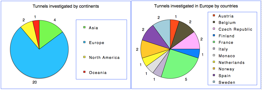
Fig 1 : Distribution of tunnel complexes within the case study and detailed distribution in Europe
The European tunnels seem over-represented in the sample analysis. This is due to,
The key information outlined in the analysis focuses on the following aspects:
From the analysis of information, the working group established a number of preliminary recommendations. These recommendations will be the subject of detailed additional developments which will be published in Part B of the report at the end of the 2016-2019 cycle.
These preliminary recommendations, presented in Chapter 11 - Present Situation, Comments and Preliminary Recommendations of the report, deal with the following aspects:
Underground road networks are located mainly in urban areas, and their design (in particular their alignment) has several constraints.
Geometric conditions which often contribute to traffic incidents, include: meandering curved alignment, insufficient visibility near the access and exit areas, insufficiently defined characteristics of merging or diverging lanes and, poorly designed exit ramp connections towards the surface road network leading to congestion in the main tunnel, etc.
It is recommended that in preparing the alignment, the following be considered:
b - Cross-section
The investigations mentioned above show that 80% of analysed tunnels prohibit the transit of vehicles that weigh over 3.5 tonnes (or 12 tonnes, in some instances). However, the tunnel design does not take into account this restriction, and does not reconsider optimisation of the lane width as well as vertical height clearance.
Investigations carried out on recent projects show that substantial savings (from 20% to 30% depending on the final design characteristics) can be obtained by choosing a reduced vertical height for tunnels that prohibit heavy vehicle usage.
It is recommended that at the earliest stage for developing tunnel projects detailed studies be undertaken to consider and analyse the “function” of the tunnel, traffic conditions (volume and nature of vehicles), as well as the financial feasibility and financing methods. This should be done in such a way as to analyse the advantages of a cross-section with reduced geometric characteristics. This may facilitate the financial optimisation of the project without reducing the level of service or affecting the safety conditions.
c - Ventilation
Underground road networks are usually subjected to large traffic volumes. Traffic congestion is frequent, and the probability of a bottleneck developing within the network is high and recurring. As a result, the ventilation system has to be developed with a detailed analysis of the risks and dangers, taking into account the existence of bottlenecks.
A “pure” longitudinal ventilation system is rarely the appropriate sole response to all the safety requirements, especially in the scenario of a fire located upstream of congested traffic. A longitudinal ventilation system will cause smoke de-stratification downstream of the incident location. This constitutes a danger for any tunnel user blocked or in slow moving downstream traffic.
The addition of a smoke extraction gallery or the choice of a transverse or semi-transverse ventilation system is often vital if no other realistic or feasible safety improvement measures can be put into place, and considered as efficient.
It is also necessary to implement equipment allowing the different network branches to operate inde-pendently of each other. This will facilitate the control and the management of smoke propagation during a fire incident.
The risks associated with dangerous goods vehicles travelling through a tunnel with a high urban traffic density must be carefully analysed. There are no ventilation systems capable of significantly reducing the effects of a dangerous goods large fire in such traffic conditions.
d - Firefighting
The necessary timeframe for response teams to arrive on site must be subjected to a detailed analysis under normal and peak hour traffic conditions. The objective is to determine whether or not it is necessary to install first line intervention facilities and resources in proximity of the tunnel portals.
The turnover of fire brigade staff is relatively high in urban areas and their interventions in tunnels are relatively rare. The high rate of turnover may lead to loss of specialist skills in tunnel intervention. Thus, it is essential to implement tools which allow continuous professional education and training of the teams. A virtual 3D model of the network, associated with simulation software, can provide pertinent, user-friendly and effective tools.
e - Signage
It is fundamental to ensure clear visibility of the exit ramps and a clear legibility of signage, in order to reduce the risk of accidents where exit ramps diverge from the main carriageway.
The locations of interchanges, entry and exit ramps, as well as the concept for signage should be analysed from the conceptual alignment studies.
f - Environment
In order to reduce atmospheric pollution, communities, stakeholders and residents often demand the installation of filtration devices for in-tunnel air before it is released into the atmosphere.
This results in a decision to install filtration equipment which is rarely rational or technical, but an ad-hoc response to public pressure. Before any decision-making on this issue, it is, however, essential to:
g – Traffic conditions – Traffic management
The connections between exit ramps and the surface network must be equipped in a way which allows supervision and management of traffic in real time. This arrangement allows traffic congestion to be reduced inside the tunnel, and an improvement of safety should tunnel incidents require quick evacuation of users.
h - Operation
The coordination between operators of physically connected infrastructure is in general adequate. However, it is often essential to improve this coordination by clarifying the situation and role of each operator (particularly in the event of traffic congestion and fire incident) by defining common procedures and determining priorities between the different infrastructure parts and their traffic.
Monographs have been established for each of the structures listed in the table below. They are accessible in the Multimedia Kit at the bottom of the page. The monographs of the structures highlighted in amber are in the process of being updated and will be online shortly.
| Continents | Countries | Cities | Names of the tunnels complex | Appendices |
|---|---|---|---|---|
| Asia | China (CHN) | Changsha | Yingpan Tunnel | 1-1 |
| Chongqing | Underground Ring Road of Jiefangbei CBD | 1-5 | ||
| Japan (J) | Tokyo | Chiyoda | 1-2 | |
| Yamate | 1-3 | |||
| South Korea (ROK) | Seoul | Shinlim-Bongchun and Shinlim-2 | 1-4 | |
| Europe | Austria (A) | Vienna | Kaisermühlen | 2-1 |
| Belgium (B) | Brussels | Leopold II | 2-2 | |
| Belliard | 2-3 | |||
| Czech Republic (CZ) | Prague | Blanka Tunnel complex (3 tunnels) | 2-4 | |
| Mrazovka and Strahov | 2-5 | |||
| Finland (FIN) | Helsinki | KEHU - service tunnel | 2-6 | |
| France (F) | Annecy | Courier | 2-7 | |
| Ile-de-France | Duplex A 86 | 2-8 | ||
| Lyon | Croix-Rousse (road tunnel + multimodal tunnel) | 2-9 | ||
| Paris La Défense | A14 / A86 motorway interchange | 2-10 | ||
| Voie des Bâtisseurs | 2-11 | |||
| Germany (D) | Düsseldorf | Kö-Bogen Tunnel | 2-21 | |
| Italy (I) | Valsassina | Valsassina tunnel | 2-12 | |
| Monaco (MC) | Monaco | Sous le rocher tunnel (2 interconnected tunnels with “Y” form layouts) |
2-13 | |
| Norway (N) | Oslo | Opera tunnel (chain of 4 tunnels) | 2-14 | |
| Tromsø | 3 interconnected tunnels with roundabouts and access to parking lots |
2-15 | ||
| Spain (E) | Madrid | M30 By-pass | 2-16 | |
| M30 Rio | 2-17 | |||
| AZCA Tunnel | 2-22 | |||
| Cuatro Torres Tunnel | 2-23 | |||
| Sweden (S) | Stockholm | Ring Road – Northern link | 2-18 | |
| Ring Road – Southern link | 2-19 | |||
| The Netherlands (NL) | The Hague | Sijtwendetunnel (chain of 3 tunnels) | 2-20 | |
| North America | Canada / Quebec (CDN) / (QC) | Montreal | Ville-Marie and Viger tunnels | 3-1 |
| USA |
Boston | Boston Central Artery | 3-2 | |
| Seattle | Seattle Interstate 90 Mt Baker Tunnel | 3-3 | ||
| SR 99 Alaskan Way Viaduct Tunnel through Seattle | 3-4 | |||
| Oceania | Australia (AUS) | Brisbane | M7 Clem Jones Tunnel (CLEM7) | 4-1 |
“Underground Road networks” are “complex systems”. All the recommendations presented in the 5 first pages of Chapter "Strategic issues" are applicable to them. Nevertheless, certain “subsets” and “parameters” mentioned in the page "Tunnel: a complex system" present a much more significant potential impact on underground networks. The “interactions between parameters” (see its section 2.2) are generally and much more extended and complex.
Several major strategic challenges presented in the above references, as well as their principal interactions, and the additional parameters below, must be well considered in the process of developing tunnel designs and for the construction and operation of tunnels.
This term is applicable to tunnel cross-section, vertical alignment, implementation of interchanges, access and exit ramps. In addition to the recommendations from section 1 of page "General design of the tunnel (new tunnel)" the following elements should be considered for:
a – Land occupation
Land occupation deals with the surface occupation in open air (roads, buildings and various structures, parks and protected areas, etc.) and the volumetric occupation of the underground space (underground infrastructures such as metro, car parks, various networks, building foundations, etc.)
The interfaces between the underground and surface spaces are numerous: ventilation stacks, access and exit ramps, evacuation corridors and intermediate emergency access.
The underground and surface land occupation constraints are not always compatible with a given location and it is often necessary to decouple surface structures from those underground. This relationship can be implemented through inclined shafts or underground corridors that link any vertical shafts that are located away from the tunnel alignment.
b - Geology, geotechnical, hydrogeology
The geological, geotechnical and hydrogeological conditions have a significant impact on the horizontal and vertical alignment especially with regard to the risk of settlement, the possibility of construction underneath existing structures and any required maintained distances to existing surface or underground structures, in relationship with the construction methodology considered.
These conditions can also influence the position of underground interchanges. For example, in the case of loose soil below groundwater level a localised widening of the cross section to build ramp merge and diverge areas could require construction works starting from the surface (large shafts, treatment and land consolidation works). These works require setting up temporary occupation on the surface. Under such conditions the location of underground interchanges should then also consider the type of land occupation on the surface.
c - Functionality for traffic
The functionality of the alignment mainly deals with areas where connection to the road network at the surface (or possibly with other underground structures) has to be built. The position and the design of the main tunnel portals, the access and exit ramps, as well as the location of interchanges depend on these functionalities.
The location of all these connections is also linked to the volume of traffic in the underground network, as well as its multiple entrances and exits. The connections must take into account the absorption capacity of traffic in the surface road network, adjustments to connections design in order to avoid underground traffic congestion and thus reduce accidents and significant tunnel fire incident risks.
d - Safety – Risks of accidents
The analysis of existing networks demonstrates a concentration of accidents around areas with curved geometry, overly steep slopes and insufficient visibility around the merge and diverge areas of ramps.
All these elements must be carefully taken into account from the early stage of the design of the horizontal and vertical alignments of a new network.
e - Methods of construction – Time period
The construction methodology has a direct impact on the horizontal and vertical alignments (and vice-versa). They are also strongly guided by the geological, geotechnical and hydrogeological conditions.
The methods of construction can have an important impact on the location of the tunnel portals. In particular, the use of a shield (slurry shield or earth pressure balanced) requires significant site area not only for the assembly of a tunnel-boring machine but also throughout the duration of the works (particularly for the treatment of slurry and provisional storage). A conventionally bored tunnel (when soil conditions permit it) requires fewer facilities close to the portal, and can be accommodated in a smaller site area.
The analysis for the shortening of construction timeframes can have an impact on the horizontal and vertical alignments, for example in order to make possible intermediate construction access sites.
f – Environmental conditions
During the operation period of the network, the main concerns are air quality and noise impacts. These concerns have repercussions on the positioning of tunnel portals and ventilation shafts. These issues must be analysed carefully, in particular the ventilation plants as well as the additional equipment likely to reduce the environmental impact.
The position of portals, and the associated temporary work site plants, must also be analysed from an environmental aspect in terms of construction methods and timeframes. For example, a conventional method of construction will have a more significant noise impact as opposed to a TBM construction method. If the tunnel portal is situated in a noise sensitive area, works will have to be suspended during quieter night periods, leading to a prolonged construction period and consequent inflation of costs. A modification of the portal location or changes to the alignment can reduce these impacts.
In addition to the recommendations from section 2 of the page "General design of the tunnel (new tunnel)" the following elements should be considered for:
a – Nature of traffic - Function
As mentioned in section 2.4.b above, the nature of traffic is a factor that must be carefully analysed regarding their initial conditions as well as its evolution over time. Many urban underground networks prohibit heavy vehicles (more than 3.5 t or 12 t depending on different conditions), even though they were designed with standard vertical height clearance and lane width characteristics (defined for the allowance of all types of vehicles).
Analysis of the “function” of the underground network and the evolution of that function is essential. It allows the cross-section to be optimised by choice of geometrical characteristics (vertical height clearance and lane width) to ensure adequacy for the present and future traffic that will use the network.
Savings made regarding construction costs are significant (from 20% to 30% depending on the chosen characteristics). Where applicable, these savings may allow a project to be financed, and thus feasible, where it may not have been with standard vertical clearances and lane width.
b - Volume of traffic
The volume of traffic is the determining factor in defining the number of lanes of the main tunnel, as well as interchange or access and exit ramps.
The volume of traffic should be taken into account when defining the length of merging and diverging lanes for entrances and exits. The risk of congestion, at the connection of exit ramps to the surface network, must also be considered, as well as the consequences that this has on the main tunnel (bottleneck queue) to determine whether or not it is necessary to design and lengthen a parallel lane upstream from the divergence point of the exit ramp from the main road.
c - Ventilation
The ventilation galleries to be installed inside the structure contribute considerably to the spatial requirement. Therefore, it is necessary to proceed to a preliminary “analysis of hazards and risks”, and an initial sizing of ventilation installations before definitively setting the characteristics of the functional cross-section. This approach is often iterative.
d – Geology - Geotechnics - Hydrogeology - Methods of construction
The geological, hydrogeological and geotechnical conditions, as well as methods of construction (which are often interlinked) have a vital impact on the shape and surface area of the cross-section. The following example illustrates this interaction.
In loose soil below groundwater level, the use of a shield will be required for the construction of the main tunnel. The main tunnel will be circular in shape. However, the cross-section will also depend on other functions:
Recommendations in section 3 of page "General design of the tunnel (new tunnel)" are also applicable to “underground road networks”. The analysis approach must, nevertheless, take into account the complexity of underground networks and the aggravating influence of certain factors, in particular:
a - Traffic
The volume of traffic is generally more significant and in high traffic volume conditions traffic congestion is much more frequent. It follows that the number of persons in the tunnel is much higher and in the event of an incident, the number of users to evacuate will be more significant.
Ramp merge and diverge areas are important locations in terms of risk of accidents.
The assumption, which is sometimes prevalent from the start of projects, that there will never be a traffic blockage must be analysed with much circumspection. It is indeed possible to regulate the volume of traffic entering into an underground network in order to eliminate all risk of bottlenecks. Nevertheless, this leads to a significant decrease in the capacity of the infrastructure (in terms of traffic volume) which often goes against the reasoning that justifies its construction. Over time, measures of reducing entering traffic must be relaxed, or even abandoned because of the need to increase traffic capacity. The probability and recurrence of bottlenecks increase, disregarding the initial assumption upon which the network was based (particularly in terms of safety and ventilation during incidents).
b - Emergency evacuation – emergency access
The analysis must take into account:
c - Ventilation
The concept and design of ventilation systems must take into account:
d – Communication with users
Communication with tunnel users must be reinforced and adapted throughout the multitude of branches within the network. Communication must be able to be differentiated between the different branches according to operational needs, especially in the case of fires.
Users must be able to identify their position inside the network, which would require, for example, the installation of specific signs, colour codes, etc.
Directional signs and prior information signs at interchanges or ramps must be subjected to careful consideration, particularly the visibility distances with regard to signals and the clear legibility of the signage.
e – Operational needs
Specific operational needs (see section 3.6 of page "General design of the tunnel (new tunnel)") must be adapted to the complexity of a network, to the volume of traffic and to the resulting increased difficulties of achieving interventions under traffic conditions.
Recommendations in section 4 of page "General design of the tunnel (new tunnel)" are also applicable to “underground road networks”. Nevertheless, analyses must take into account the complexities of underground road networks and the supplementary needs or conditions mentioned in section 3.
The interfaces between operators of associated or related network must be subjected to a specific analysis, particularly for all aspects concerning, on the one hand, traffic management and, on the other hand, safety (especially fire incidents), including evacuation of users and intervention of emergency response agencies in response to fire incidents.
Control centres must take account of the interfaces within the network and between diverse operators. They must allow the transmission of common information which is essential to each operator, and facilitate the possible temporary hierarchy of one control centre over another. The architectural design of the network of control centres, and of their performance and methods, must be subjected to an overall analysis of organisations, responsibilities, challenges and risks. This analysis should reflect a range of operational conditions such as during normal and emergency scenarios and should review the interaction between the different subsections of the network and the respective responsibilities of each control centre.
Countries that have many tunnels are endowed with regulations and have developed recommendations and guidelines for the design, construction, operation, maintenance, safety and the intervention of the rescue services.
Concerning safety conditions in road tunnels, countries belonging to the European Union are subjected to Directive 2004/54/CE that prescribes a minimum level of arrangements to be implemented in order to ensure the safety of users in tunnels longer than 500 m that are part of the trans-European road network. A wider group of European countries are also bound by an international convention, The European Agreement concerning the International Carriage of Dangerous Goods by Road (ADR) and includes specific arrangements for tunnels. Every member country has transposed these European regulations to its own national legislation. Some member countries have implemented additional regulations that are more demanding than the one that results from the transposition of the European regulation.
A list of the regulations and recommendations concerning the operation and the safety of road tunnels has been established in cooperation between the PIARC and the ITA Committee on Operational Safety of Underground Facilities (ITA-COSUF) of the international tunnelling and underground space association (ITA - AITES). This document can be consulted on the ITA-COSUF (Publications) web page. This list is not exhaustive but presents an international panel of twenty-seven countries and three international organisations.
Many countries do not have any regulations relating to tunnels and to tunnel safety, because they do not have road tunnels within their territory. It is recommended that these countries choose a complete and coherent package of the existing regulations of a country with lengthy experience in the field of tunnels, and not to multiply the origins of the documents by dipping into different sources. The recommendations of PIARC, as summarised in the present manual, as well as those of European directive 2004/54/EC also constitute international references that are being applied increasingly often.
For a tunnel to operate sustainably and ensure good comfort and safety to users, it is imperative that the entities which will be in charge of its operation are closely involved in the design phase. This chapter reviews the main elements which ensure good design of a tunnel.
In 1974, the ITA (International Tunnelling and Underground Space Association) was created to address construction aspects of all types of underground works, including road tunnels. In 2005, a Memorandum of Understanding was signed between PIARC and the ITA to ensure that their actions are and remain complementary and do not overlap. PIARC deals with tunnel geometry while the ITA takes care of purely constructional aspects.
The page on Construction presents the main tunnel construction methods and their interfaces with geometry and safety aspects. For more information concerning pure construction aspects, the reader is invited to consult the ITA Website.
The page on Theoretical and practical tunnel traffic capacity gives a summary of the theoretical notions related to traffic capacity.
The page on General alignment of roads and national examples recalls the main rules concerning the general alignments of roads, including the main figures used in some countries, and insists on the need to maintain the largest geometrical characteristics of the outside road in the tunnel itself (with the important exception of the maximum slope, which has to be limited).
The page on Carriageway geometry deals specifically with the transverse profile of the carriageway of road tunnels, for uni- as well as bidirectional types.
Emergency exits are provided in all except the shortest tunnels to allow tunnel users to evacuate on foot from the traffic tube to a place of safety. The different types of emergency exits for pedestrians are considered in the page on Emergency exits. These include cross-connections and cross-passages between tubes, and safety galleries (passages) constructed alongside the traffic tubes or perhaps under the carriageway and leading to the surface.
The page on Facilities for vehicles considers the facilities provided for vehicles. These include lay-bys, turning bays and cross-connections between tubes for vehicles, which cater for situations such as vehicle breakdowns or allow vehicles to turn around or cross into an adjacent tube, which could be useful for maintenance, for manoeuvring emergency vehicles during an incident, or for traffic management following an incident.
The page on Other facilities describes other facilities that may be provided within or at the portals of a tunnel.

Ventilation in tunnels has two functions:
Historically, the first reason for installing ventilation systems in tunnels was the reduction of pollution levels. Although the emissions of pollutants by road vehicles have decreased dramatically over the last decades, this function is still important and must be paid close attention at the design stage. In some cases, natural ventilation due to the piston effect of moving vehicles may be sufficient to fulfil the air quality requirements in normal operation. The need for a mechanical ventilation system is assessed considering, among other factors, the length of the tunnel, traffic type (bidirectional or unidirectional) and conditions (possibility of congestion) and type of vehicles.
The same factors determine the requirements for ventilation in emergency situations, especially fire. The presence of other equipment or facilities (emergency exits for example), should also be taken into account. Natural ventilation might be sufficient in some cases, but mechanical ventilation is often required for tunnels over a few hundred meters in length.
In addition to these major aspects, environmental issues linked to ventilation, issues relating to energy consumption and the related carbon footprint need to be considered. Those are linked to the localised, concentrated discharge of polluted air from the portals and stacks. Reducing their impact on the tunnel surroundings is part of good environmental design.
The following chapters describe key aspects to be taken into consideration for a proper design and operation of ventilation systems in road tunnels.
The page on Ventilation principles presents the strategic elements that must be taken into account before making a decision concerning the choice or the design of a tunnel ventilation system.
The page on Design and dimensioning describes the main criteria to be considered for the design and sizing of ventilation systems in road tunnels, covering both normal and emergency ventilation.
The page on Control and monitoring examines some specific aspects related both to the tunnel ventilation system and the control system and SCADA.
Other aspects related to tunnel ventilation equipment can be found in the pages Ventilation and Tunnel Ventilation Systems within the page on Equipment and systems.
And last, but not least, additional considerations related to tunnel operation are given in the page on ventilation strategies . These are essential to ensure that all actions required are handled in a consistent and safe way, recognising that the level of safety provided for tunnel users is highly dependent upon the specific characteristics of the tunnel, but also depends strongly on operational procedures which need to be taken into account for each tunnel.
The design of tunnel ventilation systems aims to select the best choice in order to face the following challenges:
Taking into account the volume of air required for the dilution of pollutants as well as other factors, such as tunnel length, location, type of traffic, environmental laws, and not least, fire safety considerations, an assessment can be performed and the ventilation system can be chosen for each particular tunnel.
Many different types of ventilation systems can be identified in road tunnels including, among others, the following:
(combinations of the above systems are possible and, in some cases, unavoidable):
A description of the main characteristics of each of these systems can be found in Chapter V "Ventilation for fire and smoke control" of the 1999 PIARC report 05.05.B, Chapter 4 “Ventilation” of the PIARC report 2007 05.16.B Systems and equipment for fire and smoke control and Chapter "Classification of ventilation Systems" of 2011R02 PIARC report Road Tunnels: Operational Strategies for emergency ventilation.
Criteria and methodologies for the design and dimensioning of tunnel ventilation can be found on the page "Design and Dimensioning", which are based on the main basic ventilation principles, applicable to normal operation and fire scenarios, as described in the following sections.
The emissions of CO, particulate matter and NOx (the sum of NO and NO2) are considered the reference pollutants from internal combustion driven vehicles in road tunnels.
The required amount of fresh air for a given traffic situation in the tunnel depends on the number and type of vehicles in the tunnel, the average emission per car in this traffic and the admissible concentration for this particular emission (see PIARC report 2019 R02 Vehicle emissions and air demand for ventilation).
For those contaminants affecting human health, exposure time dependent threshold values can be imposed by jurisdictions. The pollution dosage depends on the travel time required to pass through the tunnel. In the absence of national regulations, Chapter 4 “Design and Operational pollutant values” of the PIARC report 2019 R02 PIARC report “Vehicle emissions and air demand for ventilation” recommends admissible concentration and operation (normal and maintenance) limits.
Additional information on NOx emissions and derived recommendations in relation to tunnel ventilation in road tunnels can be found in the PIARC report 2000 05.09 “Pollution by nitrogen dioxide in road tunnels”.
Moreover, for environmental reasons, the ambient air quality at tunnel portals is often required to adhere to certain thresholds of pollutants, mainly NO2. This can be achieved by portal air emissions management. The requirements for in-tunnel air quality or ambient air quality at the tunnel portals may determine, in some cases, the capacity requirements of the ventilation system.
The page on "Design and dimensioning" describes the main criteria to be considered for the design and sizing of ventilation systems in road tunnels for normal operation.
In addition, during the operation of the tunnel, the control of the ventilation system is established according to set points, generally lower than admissible concentration limit values, so tunnel ventilation is engaged prior to pollutant levels exceeding criteria. For extreme circumstances, tunnel closure threshold values that should never be exceeded are defined for safe operation of the tunnel. Further information on design of ventilation control systems can be found on the page "Control and monitoring".
An understanding of how smoke behaves during a tunnel fire is essential for every aspect of tunnel design and operation. This understanding will influence the type and sizing of ventilation system to be installed, its operation in an emergency and the response procedures that will be developed to allow operators and emergency services to safely manage the incident.
Chapter 1 "Basic principles of smoke and heat progress at the beginning of a fire" of the PIARC report 2007 05.16.B "Systems and equipment for fire and smoke control" presents details of the general behaviour of smoke and the major influences that affect its propagation in a tunnel, while Chapter 3 describes real case experiences on the influence on smoke control of tunnel ventilation operation in case of fire.
Since a tunnel can be used by different vehicles such as cars, buses, trucks, special vehicles, etc., which may have different loads (persons, non-flammable, flammable, explosives, toxic goods, etc.), possible tunnel fires may differ in terms of quantity and quality. In most cases they are relatively harmless, small tunnel fires with minor temperature and smoke development, but very dangerous tanker fires with high temperatures, enormous smoke production and the danger of explosion may occur. Therefore, it is not possible to prescribe the temperature and smoke development for every possible kind of tunnel fire.
The development and dispersal within the tunnel of smoke resulting from fires depend mainly on the following factors:
Basically it can be said that due to the heat released around the fire site, the smoke rises to the ceiling, and that it continues its flow in one direction when the longitudinal velocity is high, with or without backlayering (see the section on "Dimensioning" of the page on "Design and dimensioning") and in both directions when the longitudinal velocity is low. Thus, there should be some smoke-free space just above the road surface in the vicinity of a fire - at least for a short period of time.
Detailed information on smoke and pollutants production during real fires and large scale fire tests can be found in Section II.4 "Choice of design fires" and Section III.4 “Smoke development and dispersal of smoke in fire tests” of the 1999 PIARC report 05.05.B "Fire and Smoke control in Road Tunnels" and in Appendix 2 "Fire tests" of the 2017 R01 PIARC report "Design Fire characteristics for Road Tunnels".
Tunnel ventilation is a key element to mitigate the consequences of a fire in a tunnel. The page on "Design and dimensioning" describes the main criteria to be considered for the design and sizing of ventilation systems in road tunnels for fire scenarios.
In addition, the page on "Ventilation Strategies" provides additional information on the best operational strategies in case of fire.
A very important risk factor when dealing with fire safety in a tunnel is whether vehicles transporting dangerous goods are allowed or not. The criteria to decide when such transport should be allowed are not usually covered in the topics related to tunnel ventilation. Further information on the assessment an mitigation of the risks associated to the transport of dangerous vehicles in road tunnels can be found on the page "Hazards due to DG-transport".
The ventilation design process basically includes the choice of the type of ventilation system, the computation of the minimum acceptable capacity of the system in terms of thrust and/or flow rates, the design of the ventilation network and the selection of appropriate ventilation equipment, which should meet a number of specifications, including resistance to fire and acoustic performance.
The choice and design of a ventilation system depends on these main factors:
The page on "Ventilation principles" provides general information on the different types of ventilation systems that can be found in road tunnels.
A natural ventilation system can be very effective for the dilution of pollutants (especially for unidirectional tunnels), but it is not possible to rely upon natural ventilation for safety purposes for tunnels over a few hundred meters in length. Because of the number of contradictory design parameters, it is not possible to express universal recommendations about the limits of the natural ventilation.
In most countries, the need for a mechanical ventilation system during normal operation is assessed considering the length of the tunnel and the traffic type (bidirectional or unidirectional) and conditions (possibility of congestion). The same factors determine the requirements for ventilation in emergency situations, especially fire. The presence of other equipment or facilities, emergency exits for example, should also be taken into account.
Generally speaking, two types of ventilation strategies can be found:
In order to decide between longitudinal ventilation (LV) and transverse ventilation (STV/TV) for a given tunnel situation, these are some of the arguments:
Further information on the impact of tunnel ventilation in the overall operational costs and energy consumption can be found in the PIARC report 1999 05.06 Road Tunnels: Reduction of operating costs
Nowadays, the choice between the different ventilation system choices is mostly guided by fire safety considerations although environmental aspects are gaining importance during the decision taking process. In sections V.7 “Recommendations on longitudinal ventilation” and V.8 “Recommendations on transverse and semi-transverse ventilation” of the 1999 PIARC report 1999 05.05 "Fire and Smoke Control", relevant design criteria and description of the main limitations can be found.
PIARC report 2007 05.16 "Systems and equipment for fire and smoke control in road tunnels" analysed additional aspects related to this type of systems. Thus, section "4.4 Longitudinal ventilation" includes criteria and guidelines for the design and testing of this type of system, including considerations regarding the sound levels to be reached in the tunnel environment ("4.4.2 Sound Impact of Jet Fans in a Tunnel").
Furthermore, the design of ventilation systems has to cover other project-wide topics including availability, durability, maintainability or reliability. Some guidance and considerations on life cycle cost for ventilation systems can be found in the PIARC report 2012 R14 "Life Cycle Aspects of Electrical Road Tunnel Equipment".
The section on "Ventilation during normal operation" of the page on "Ventilation principles" presents some general background information of interest in relation to normal operation in road tunnels.
The design of a road tunnel ventilation system must consider fresh-air demand for maintaining in-tunnel air quality during normal and congested traffic operations and the control of smoke and hot gases in case of fire. The ventilation capacity to manage a fire incident frequently drives the ventilation sizing in highway and non-urban tunnels. Nevertheless, the fresh-air requirement for dilution during normal and congested operation, or special environmental constraints, can be dominant in tunnels with high traffic volumes and frequent congested traffic.
The ventilation capacity for normal operation is defined by the air demand required to dilute vehicle emissions to maintain allowable in-tunnel air quality values.
The fresh-air demand (airflow rate) is determined by the allowable increase of emission concentrations within the airflow. Air enters the tunnel environment with ambient pollutant concentrations. As this air moves through the tunnel environment, tailpipe emissions increase the pollutant concentrations. The vitiated air must then be diluted within the tunnel environment prior to reaching admissible pollutant limits. Emission concentrations within the tunnel are the product of the emission rates and the inverse of the airflow.
The required amount of fresh air for a given traffic situation in the tunnel depends on the number of cars in the tunnel, the average emission per car in this traffic and the admissible concentration for this particular emission.
Several PIARC reports dealing with the topic of design and dimensioning of tunnel ventilation for normal operation have been published during the last decades. The PIARC report 1996 05.02 “Road Tunnels: Emissions, Environment, Ventilation" defined a method for the calculation of the fresh-air demand and to provide emission rates for tunnel ventilation design, and in addition some general and specific information which may be useful when designing a longitudinal or semi-transverse ventilation system were provided.
However, due to the continual renewal of the vehicle fleet, a steady tightening of emission laws and the introduction of alternative propulsion systems (hybrid vehicles, electric cars, etc.) design emissions data required constant updating. As a result, new versions of the 1996 report were published in 2004, 2012 and the latest in 2019 (see PIARC report 2019 R02 “Vehicle emissions and air demand for ventilation”), which provide new methods for the calculation of the fresh-air demand and emission rates on an international basis.
The emission rate is a function of several factors including:
A detailed description of the method for the calculation of the emission generation rate (section 5) and the latest version of the database can be found in the 2019 emissions report. For practical purposes an electronic format excel sheet containing the emissions data can be downloaded from the PIARC virtual library.
The section on fire scenarios of the page on "Ventilation principles" presents some general background information of interest in relation to emergency scenarios in road tunnels.
The ventilation capacity required by normal operation may not be sufficient to fulfil the requirements of smoke handling. In addition, the airflow required to achieve a sufficient control of the smoke depends on the fire size.
With the objective of defining the ventilation capacity, the design fire (defined as a Heat Release Rate or HRR, in MW, as a function of time) provides the fire characteristics that are used to establish the sizing of equipment in tunnels and the scenarios to consider when developing emergency response plans.
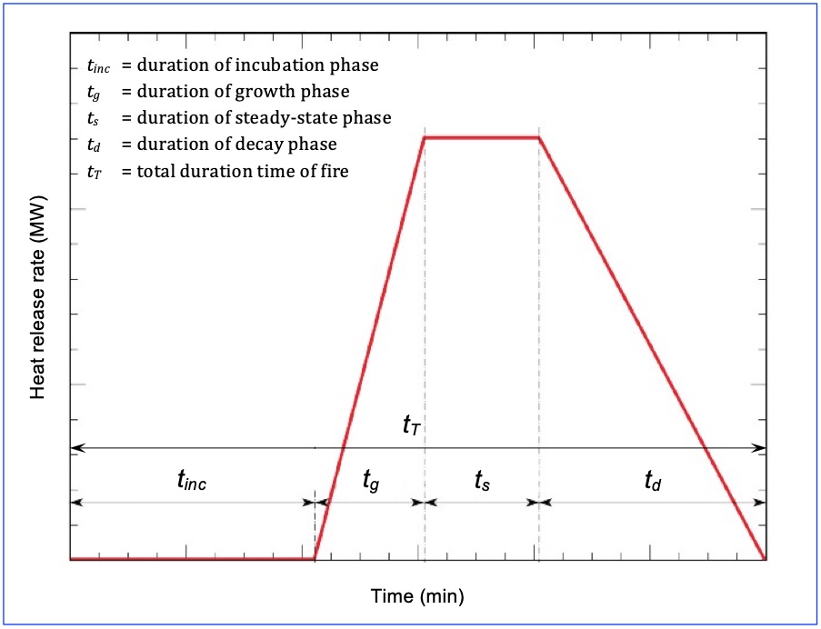
Fig. 1: Idealized HRR curve
The choice of a design fire depends on the type of traffic allowed in the tunnel. Following the 30 MW design fire peak value recommended in the PIARC report 1999 05.05 "Fire and Smoke Control", the PIARC report 2007 05.16 "Systems and equipment for fire and smoke control” restated the previously established peak heat release rates for different types of vehicles and also discussed the fire growth in the context of emergency exits.
Lately, the PIARC report 2017 R01 "Design fire characteristics for road tunnels" gave some direction to the choice of a design fire from a life-safety perspective. The report provides information on tests and the events that have brought the topic into question and also summarises the criteria for the design fire that are currently adopted in different countries.
In addition, the report presents the different approaches currently adopted in most countries for the choice of design fires in road tunnels.
Prescriptive design involves the application of a design fire given by a code or standards which may vary depending on the traffic type, density and tunnel length and location, and the designer or authority would choose the appropriate value for a given case. Section 2.1 "Summary of practices adopted in different countries" of the PIARC Report 2017 R01 "Design fire characteristics for road tunnels" summarizes the typical design-fire assumptions used in different countries.
In a performance-based approach a process of design assessment will establish levels of risk that are acceptable. The starting point may be the prescriptive values adopted, modified in the light of mitigation measures and acceptable risk levels.
Between these two approaches, there are intermediate options that allow a degree of performance-based design on the basis of prescriptive guidance.
The influence of Fixed Fire fighting systems in the definition and choice of a design fire is discussed in the PIARC report 2016 R03 "Fixed Fire Fighting systems in road tunnels: Current practices and recommendations".
As a conclusion, an exact universal design fire cannot be specified; indeed to do so would be inconsistent with the known variability and probability of differing fire sizes in tunnels. However, once it is defined for each specific case, the ventilation capacity for fire scenarios can be accordingly evaluated, with different considerations depending on the type of ventilation system.
Longitudinal ventilation
Longitudinal ventilation systems induce a longitudinal flow along the axis of the tunnel, and this provides an efficient smoke-management system as long as the tunnel is occupied only on one side of the fire, thus assuming that traffic downstream can proceed out of the tunnel. Smoke is blown toward the unoccupied side, so that egress can be carried out in the upwind direction.
This is achieved when the longitudinal ventilation is conducted at a velocity of at least the critical velocity. Too low a velocity would result in smoke propagation upstream of the fire (i.e. back-layering).
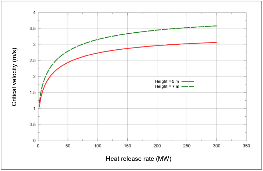
Fig. 2 : Example of the critical velocity as a function of the heat-release rate and tunnel height
Transverse ventilation
Recent developments in semi-transverse smoke extraction, aim at limiting the smoke spread on both sides of the fire. This enables egress away from the fire on either side. This method is essential in case of rescue from a fire in a tunnel with bi-directional traffic or traffic congestion. Ideally, the extraction system should cause air to flow in the traffic space, towards the fire on both sides, as shown in the figure. This confines the smoke region and increases the efficiency of extraction.
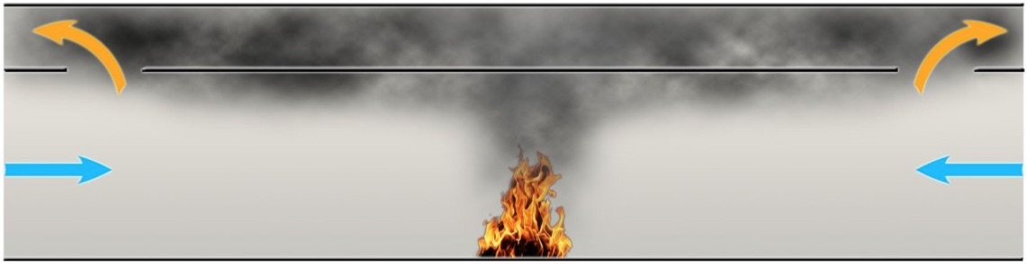
Fig.3. Principle of confinement
Some systems employ remotely controlled dampers that enable point extraction of smoke near to the fire. The construction costs for an extract system are higher than for longitudinal systems and since the required duct size increases with the heat-release rate, a larger design fire has an impact on the resulting investment costs.
Additional information on the implications on the design fire of the smoke-management can be found in chapter 3 of the PIARC report 2017 R01 "Design fire characteristics for road tunnels".
Once the type of ventilation system has been chosen and the ventilation capacity (in terms of airflow required) is determined, dimensioning of tunnel ventilation must allow the definition of the equipment precisely to deliver the required ventilation capacity both for normal operation and fire scenarios.
In general, ventilation sizing for longitudinal ventilation consist of the calculation of the required thrust for the jet fans or Saccardo nozzles, while for transverse ventilation the size of the exhaust and/or supply ducts and the air flow, pressure and electrical power of the associated axial or centrifugal fans must be estimated.
More detailed information on the ventilation equipment characteristics can be found on the page "Tunnel Ventilation System" included on the general page on "Equipment and systems".
The following general and specific information may be useful when dimensioning a longitudinal or semi-transverse ventilation system.
Longitudinal ventilation
With the help of an air-jet placed in the tunnel air column, the air flow resistance can be overcome by converting the jet momentum into static pressure. The air jets can be placed at the tunnel entrance (Saccardo), blowing outside air into the tunnel or as ducted fans along the tunnel, each one accelerating part of the tunnel air flow.
Basic formulae were given in section IV.2 "Longitudinal ventilation" of the PIARC report 1996 05.02 “Road Tunnels: Emissions, Environment, Ventilation” for sizing jet fan systems (thrust and number) used in longitudinal ventilation for normal operation, considering many factors such as the vehicle piston effect, meteorological counterpressure, resistance of the walls, etc. Considerations in jet fan design included the influence of fire on the jet fan system, the meteorological effects at tunnel portals (mainly wind), the optimal placement of the fans, the efficiency of the fans, and the sound levels created by the fan system.
PIARC report 2007 05.16 "Systems and equipment for fire and smoke control" included additional considerations to evaluate the influence of fire on a jet fan system, providing further recommendations for fan distribution along the tunnel. Of particular interest for the dimensioning of longitudinal ventilation systems is the example calculation in section 12.3.3. "Jet Fan calculation procedure", which provides detailed information on the procedure to size longitudinal ventilation systems.
Transverse ventilation
To size a transverse ventilation system for fire scenarios, two aspects must be considered:
Basic formulae are given in section IV.3 "Semi-transverse ventilation" of the PIARC report 1996 05.02 “Road Tunnels: Emissions, Environment, Ventilation” for estimating the total pressure loss along the distribution duct and ventilation stations during normal operation.
The PIARC report 1999 05.05 "Fire and Smoke Control", provides a table (see table 2.4.3) and the relevant relationship between heat release and smoke flow rates. In addition, in section V.8 “Recommendations on transverse and semi-transverse ventilation" criteria are provided for the sizing of ventilation systems of this type, including extraction capacity, the differences between distributed or concentrated extraction systems and the influence of the fresh air supply on the behaviour of the fumes.
PIARC report 2007 05.16 "Systems and equipment for fire and smoke control" included additional considerations for the choice of the ventilation equipment (see section 12.4 “smoke dampers”).
In comparison with conventional tunnels, specific design criteria that might have a significant impact on the design of the ventilation systems have to be considered in the case of urban and complex network tunnels.
The design of urban and complex tunnel ventilation systems strongly depends, among others, on the following factors:
Further information on this topic can be found in chapter 6 of the PIARC report 2016 R19 “Road Tunnels: Complex underground road networks” and in the PIARC report 2008 R15 “Urban road tunnels - Recommendations to managers and operating bodies for design, management, operation and maintenance”.
There are two principal aims of a well-designed ventilation control system:
It is therefore important to bear in mind that the objectives of the ventilation system and the associated control system are different depending on the situation of the tunnel.
Normal operation
During a normal operating situation, the levels of pollutants in the tunnel may increase (depending on the traffic conditions and the natural ventilation of the tunnel) until it becomes necessary to activate the mechanical ventilation, in which case it can be done either automatically or manually.
In order to obtain information on the levels of pollutants, carbon monoxide and visibility sensors are usually available in the tunnel, although the installation of other types of sensors such as nitrogen oxides is becoming increasingly common.
Originally, the measurements of contaminants in the tunnel were used to perform the actions on ventilation manually. In some tunnels with a low level of supervision, these actions are implemented in the tunnel monitoring and control system that carries them out automatically through a series of predefined algorithms or sequences.
However, nowadays, most tunnels have automatic ventilation control systems whose objective is not only to guarantee the required air quality levels, but also to achieve this efficiently by minimising energy consumption and equipment maintenance needs (see section 4.3 "Actions to reduce tunnel operating costs" of the PIARC report 2017 R02 "Road Tunnel Operations: First Steps towards a sustainable approach").
Where routine ventilation is concerned, an optimal air flow rate is one that satisfies two conflicting requirements; the rate of ventilation must be sufficient to dilute the pollutants generated by the vehicles, while at the same time the air flow quantities should be as small as possible in order to reduce the energy consumption at the fans and therefore reduce running costs.
The optimisation of ventilation control for air quality considerations during normal operation is crucial to reduce energy consumption. This is an important issue since this consumption represents a significant part of the operational cost of a tunnel.
The constant adjustment of air flow to cope with the needs is a difficult problem especially in the case of long and complex tunnels where the control of the ventilating airflows can be difficult to maintain.
Chapter IV "Ventilation control" of the 2000 05.09.B. PIARC report “Pollution by nitrogen dioxide in road tunnels” report describes some of the criteria usually considered and the most common criteria.
Emergency ventilation
Emergency ventilation, on the other hand, needs fast and well-targeted interventions, short response times, and a well-defined sequence of all the operations. The objectives of incident ventilation are therefore quite different from those of normal ventilation, and economic considerations are no longer the principal concern.
In a fire situation, the actions on the ventilation are normally associated with automatic detection systems or with supervision from the control centre, which allow the triggering of the action sequences for the pre-defined ventilation. Thus, ventilation control systems are one more tool in the set of tools available to mitigate the consequences of a fire situation.
For this reason, ventilation control must be considered with a global approach that takes into account the strong link between the emergency services' action procedures, the actions of the control centre operator and the tunnel results in terms of smoke behaviour. A general discussion of the importance of taking ventilation into account in the definition of fire response plans can be found in section VIII.4.1 "Fire response planning" of the 1999 PIARC report 05.05 "Fire and Smoke Control in Road Tunnels".
The design of appropriate ventilation control scenarios for each possible fire situation is a very important part of the process: see PIARC technical report 2011 R02 "Road tunnels: Operational strategies for emergency ventilation". These scenarios can be simple, especially when the purely longitudinal strategy is applied, or involve a large number of measurement and ventilation devices in complex, transverse-ventilated tunnels or in tunnels with massive point extraction for which the control of the longitudinal airflow can be necessary.
There are numerous ways and strategies to approach the design of a fire ventilation control system which depend on multiple factors such as the degree of supervision, means of detection, ventilation strategies and the type of system.
Firstly, its design must take into account the expected evolution of the incident, the different stages that occur throughout the emergency and the influence of ventilation on the behaviour of the fumes. Although in some cases the actions on the ventilation equipment are simple and do not require complex control systems, in many cases it is necessary to take into account sophisticated criteria.
Today, the development and implementation of ventilation control systems in case of fire represents an important part of ventilation design, in which the definition of the necessary control algorithms is particularly important and it is crucial to be able to guarantee the quality and reliability of field measurements (speed and smoke detection sensors).
The chapter "Response of ventilation control systems to fire" of the PIARC technical report 2011 R02 "Road tunnels: Operational strategies for emergency ventilation" provides detailed information about the challenges and needs of control systems for ventilation management and current experiences in this field.
The ‘’sustainable development’’ concept may have a slightly different meaning from one country to another and its scope may vary. However the most widely accepted concept is based on three main pillars: economic, environmental and societal.
The concept of sustainable development may be applied to different fields or sectors, including road tunnels, in particular for the operation of this type of infrastructure.
As we know, the operation of a road tunnel is highly dependent on the design and construction phases which precede its commissioning. More precisely it is necessary to take account of the effect of solutions opted for during a project’s design phase on subsequent operating conditions. In other words, this means that, if the chosen solution is not ideal, it will be very difficult to optimize it throughout the tunnel’ life cycle. The technical Report 2017R02EN "Road Tunnel operations: First steps towards a sustainable approach’’ is entirely devoted to sustainability issues and in particular, to optimizing the three pillars.
This chapter gives information about the three main pillars of the sustainable development concept. The balance between these pillars should be estimated accurately for each project design. Nevertheless we should have in mind that sustainable development represents a holistic approach of all involved sectors and parameters, as well as an acceptable and balanced weighting of economic, environmental and societal objectives.
The chapter is broken down into four pages:
A tunnel creates wealth. On a national level, the main part of this wealth creation is due to reduced travelling time, notably for goods transport. It should be noted that the economic benefits of investment in road tunnels are a very complex matter and mostly related to subjective evaluation by decision makers. However, the economic arguments behind the decision to build a tunnel will largely consider the benefits of doing so against the costs.
The potential benefits from constructing a tunnel may consider the following range of issues:
The decision-making evaluation behind the costs for installing a new tunnel will need to consider three main elements: investment, operating and maintenance costs. Construction and maintenance costs will need to consider the impacts on road user travel time and vehicle operating costs during scheme construction and for maintenance.
During the construction phase, it is necessary to ensure that all the planned technical specifications are implemented and that the identified objectives are attained. Finally, it is important to be particularly vigilant with regards to financial aspects, so as to ensure that the cost of works remains within the overall allocated budget.
The primary aim of environmental protection is to reduce the impact on air, water and ground to a long-term acceptable level.
The benefits of the construction of a tunnel should consider the greenhouse gas benefits arising from reduction in travel time and vehicle operating costs.
The preservation of the species living around the tunnel may require the set-up of special measures. These measures may be aimed at restoring passageways for certain species or preserving reproduction areas. In some cases, the position of certain technical facilities may be modified (ventilation units, extraction shafts, etc.).
In order to avoid the exceptional presence of these species on the roadway or in the tunnel (which can present significant risks for drivers and for the species in question) specific measures like fencing or enclosures may be necessary.
The use of natural resources should be carefully examined in the design phase, if possible by favouring materials which have the lowest carbon footprint, or by recycling materials already used elsewhere. Also, to minimize the use of energy resources, the design should take into account the energy consumption during both the construction phase (adapt the design to less energy-intensive construction methods) and the operational phase of the tunnel.
With regard to the three components of the environmental pillar (conservation of species, resources and energy), the construction phase has considerable impacts. A tunnel should be built in such a way that the impact on the environment is as low as reasonably practicable. Selected suppliers must:
All the actions planned for the conservation of animal species present in the vicinity of the works or in the vicinity of the finished tunnel must be undertaken in strict compliance with the environmental specifications outlined during the study phase.
The impact of a tunnel on housing conditions and health may be positive for the residents who will no longer suffer from sound nuisances as they will disappear with the construction of the tunnel. It may sometimes be negative for people living near the portals of the tunnel (if the tunnel was badly designed) who will be subjected to increased sound nuisances or higher pollution levels. The installation of noise barriers could therefore be considered a measure for sustainable road tunnel operations.
In addition, we need to examine the impact that the road tunnel may have on the economic attractiveness of areas which previously had poor access conditions.
The points mentioned above on economic appraisal should also be viewed through the lens of social benefits or costs. For instance, by creating new links with a tunnel the journey time for someone commuting to work could be greatly improved and this would yield not just economic but social benefits – for instance with greater time with family and friends through a reduced commute time.
Other aspects for consideration for sustainable options could be feasibility for walking and cycle ways with measures such as dedicated cycle ways that could be used by pedestrians also being built into the design at the outset.
From a social point of view, the construction phase can have quite different effects: either positive or negative.
For inhabitants in the vicinity of the works site, it is clear that the works can pose a nuisance (traffic disruptions, noise, dust, etc.). Suitable measures must therefore be taken to reduce such forms of nuisance, so that residents are disrupted as little as possible.
On the positive side, it is during the construction phase that the impact on employment is the greatest. Tunnel construction requires considerable manpower over a long duration, especially if the size of the tunnel is substantial. This manpower is not necessarily local, but more often than not a considerable part of this manpower is hired near to the works site. Moreover, non-local manpower has an indirect impact on the local economy (hotels, restaurants, etc.).
The main energy-consuming devices in a tunnel during normal operation are:
The respective share of each of these energy-consuming systems varies greatly, depending on the specific characteristics of the tunnel: length, gradient, water ingress, etc. Let us consider, for example, the case of a short tunnel: it will not be ventilated (therefore the ventilation element is removed), but it will be lit with entrance zones covering almost its entire length and, due to its shortness; lighting will be a major energy-consumption factor. In contrast, for very long tunnels, the energy-consumption of lighting will be low compared with the energy-consumption of the ventilation system.
In relation to energy expenditure, the first thing that an operator can do, for any given energy requirement is to play competitors off against each other by consulting several suppliers that provide the kind of electricity to be used (renewable energy). This approach assumes that the installation is optimized in terms of the power installed and the operating times of the various pieces of equipment.
In effect, we have seen that energy expenditure is closely linked to two factors: the power installed per family of equipment and each family of equipment’s operating time.
For each family of equipment, the installed power is assessed during the study phase and is fixed during the implementation phase. Once the structure is operational, the power can mainly be changed during renovation. At this time, it may be decreased if the regulations haven’t changed and if the energy performance of the replacement equipment has improved. It may be increased if regulations have become stricter (for example: greater smoke extraction capacities).
Basically, outside of renovations, if an operator wants to reduce its expenditure on electricity, it can only do so by optimizing the operating times of the installed equipment and by monitoring peak hours.