
If tunnels are longer than a few hundred metres, specific equipment is required to enhance user safety, both in normal situations and in case of accidents.
To reduce the risks of accidents and limit the possible consequences, but also to provide users with an adequate level of comfort, a large variety of equipment can be installed. Chapter 7 of the report 05.06.B "Reduction of operating costs of road tunnels" discusses road tunnel equipment and Chapter 3 of the report 2008R15 "Urban road tunnels" provides details for the design and refurbishment of equipment.
The equipment of road tunnels is most often gathered in the following groups:
This group comprises cross-functional equipment:
A significant amount of electric power is required to enable the equipment installed in the tunnel to operate. The electrical power supply systems (see page on Electrical power supply) must provide enough power for normal and emergency conditions. This also means that the system must work even in the case of blackouts, enabling vital equipment to keep functioning.
To guarantee user comfort and reduce the risks of accidents it is important to ensure adequate visibility and reduced concentration of contaminants. For these purposes, an adequate lighting system (see page on Tunnel lighting system) and ventilation system (see page on Tunnel ventilation system) are necessary. Ventilation is also crucial in emergency conditions, as it affects both fire development and smoke propagation. Depending on the traffic and the tunnel length, ventilation can be only natural, only mechanical or mixed natural/mechanical (e.g. natural in ordinary conditions and mechanical in emergency conditions).
The status of this equipment should also be monitored. For this reason, a SCADA system (see page on Supervisory Control And Data Acquisition systems (SCADA)) may be implemented.
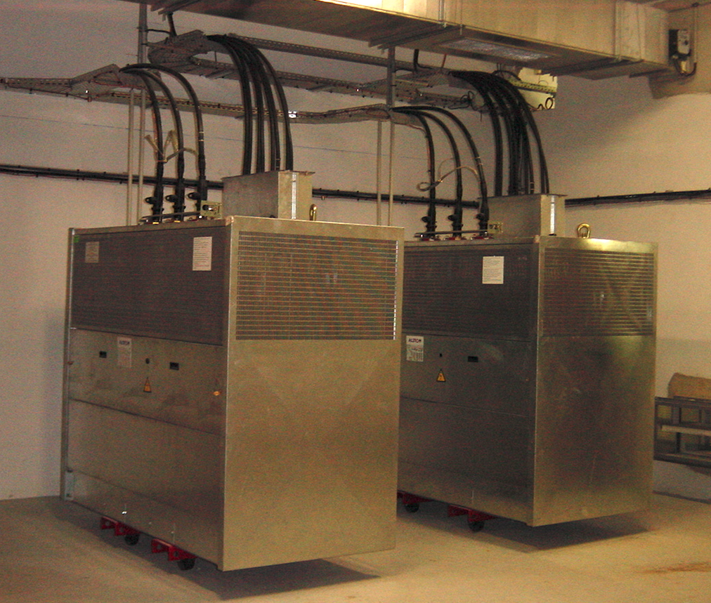
Figure 1: High voltage transformer
The power required for supplying a tunnel is directly related to the nature and number of equipment installed in it. Depending on the amount of electrical energy required (kWh), power may be supplied in low voltage or high voltage (Fig. 1).
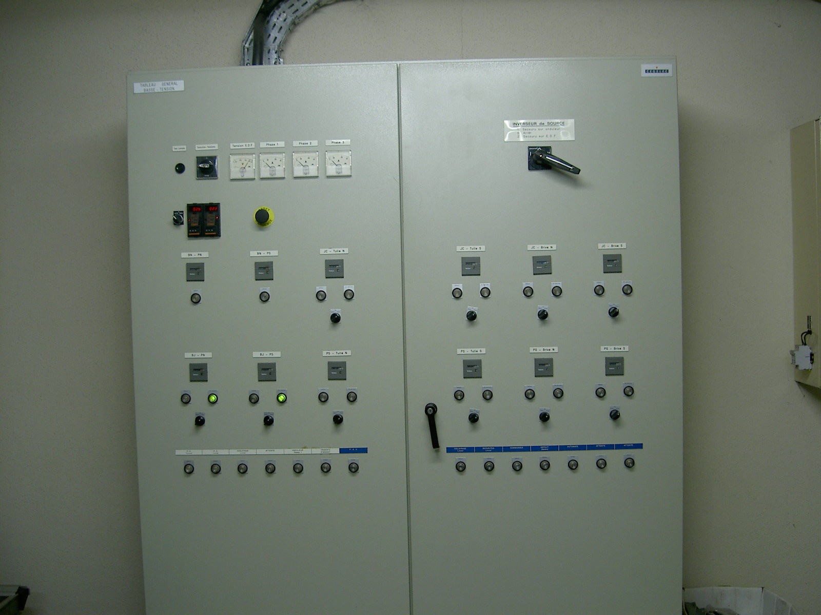
Figure 2: Example of an electrical enclosure
In the majority of tunnels, the natural penetration of light does not allow satisfactory visibility for users. It is therefore necessary to install artificial lighting to improve visibility conditions and comfort.
In terms of functionalities, the lighting installation must allow for:
Normal artificial lighting usually includes two successive zones:
In some tunnels, where there is a risk of glare at the exit, there is an exit reinforcement zone.
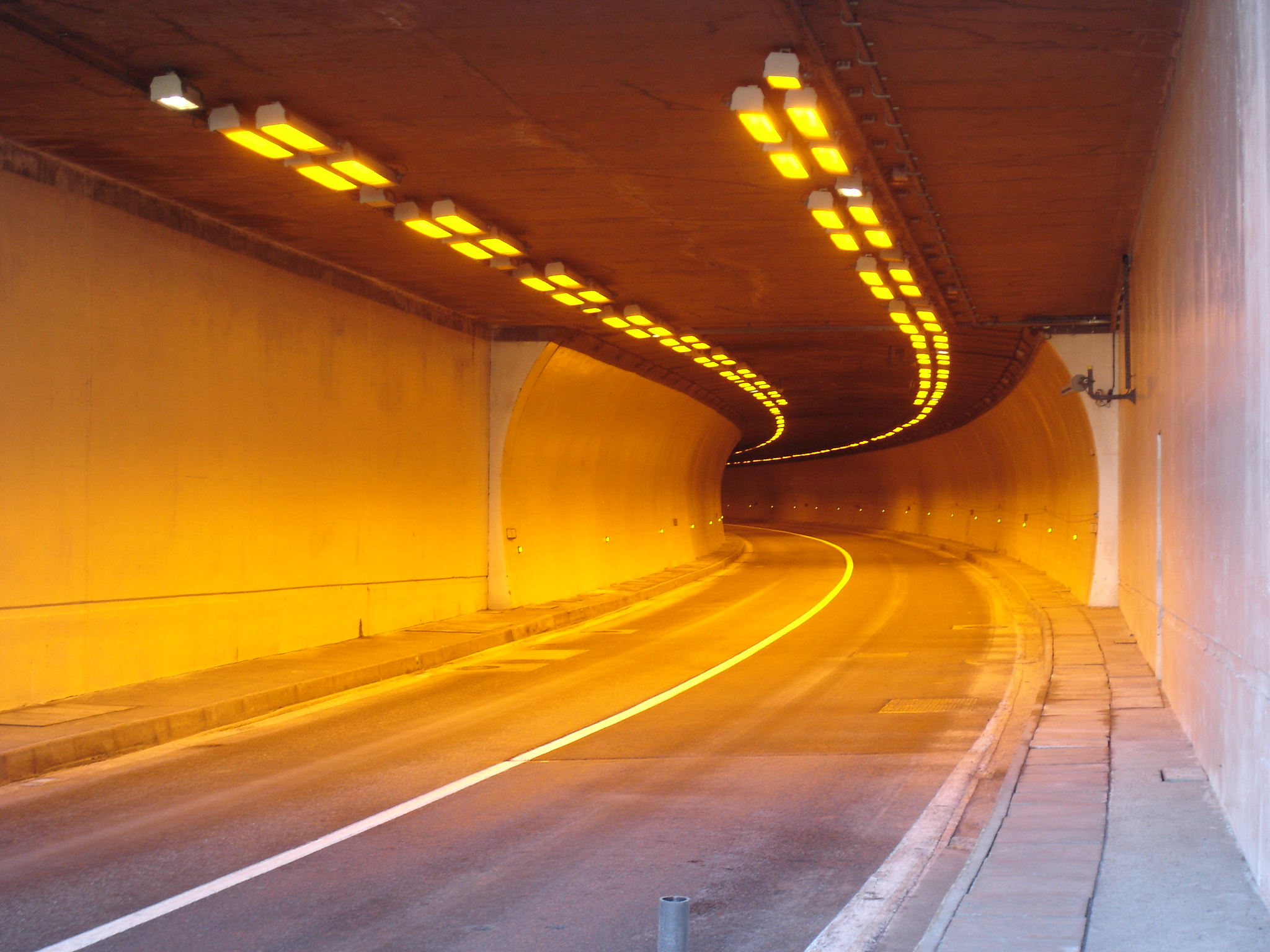
Figure 1: Example of reinforcement lighting in the Puymorens tunnel (France)
Entrance lighting
Motorists approaching a tunnel entrance will often experience what is known as the “black hole effect”. This is because luminance levels inside the tunnel are much lower than those outside and our eyes have difficulty adapting to the sudden difference. To alleviate this effect, a higher, “reinforced” level of lighting must therefore be provided at the tunnel entrance. This will ensure that drivers can see objects within the correct stopping distance before entering the tunnel. It will also help to prevent them from slowing down, which is important to maintain optimal traffic flow.
The amount of light required to avoid the black hole effect will depend on the bness outside the tunnel (sunny or cloudy weather). Luminance measurements at portals are normally used to determine and adjust the lighting levels required for the entrance zone.
In order to enable drivers’ eyes to adapt from the entrance zone lighting to the interior zone lighting, the entrance lighting level is gradually reduced as drivers move along the tunnel.
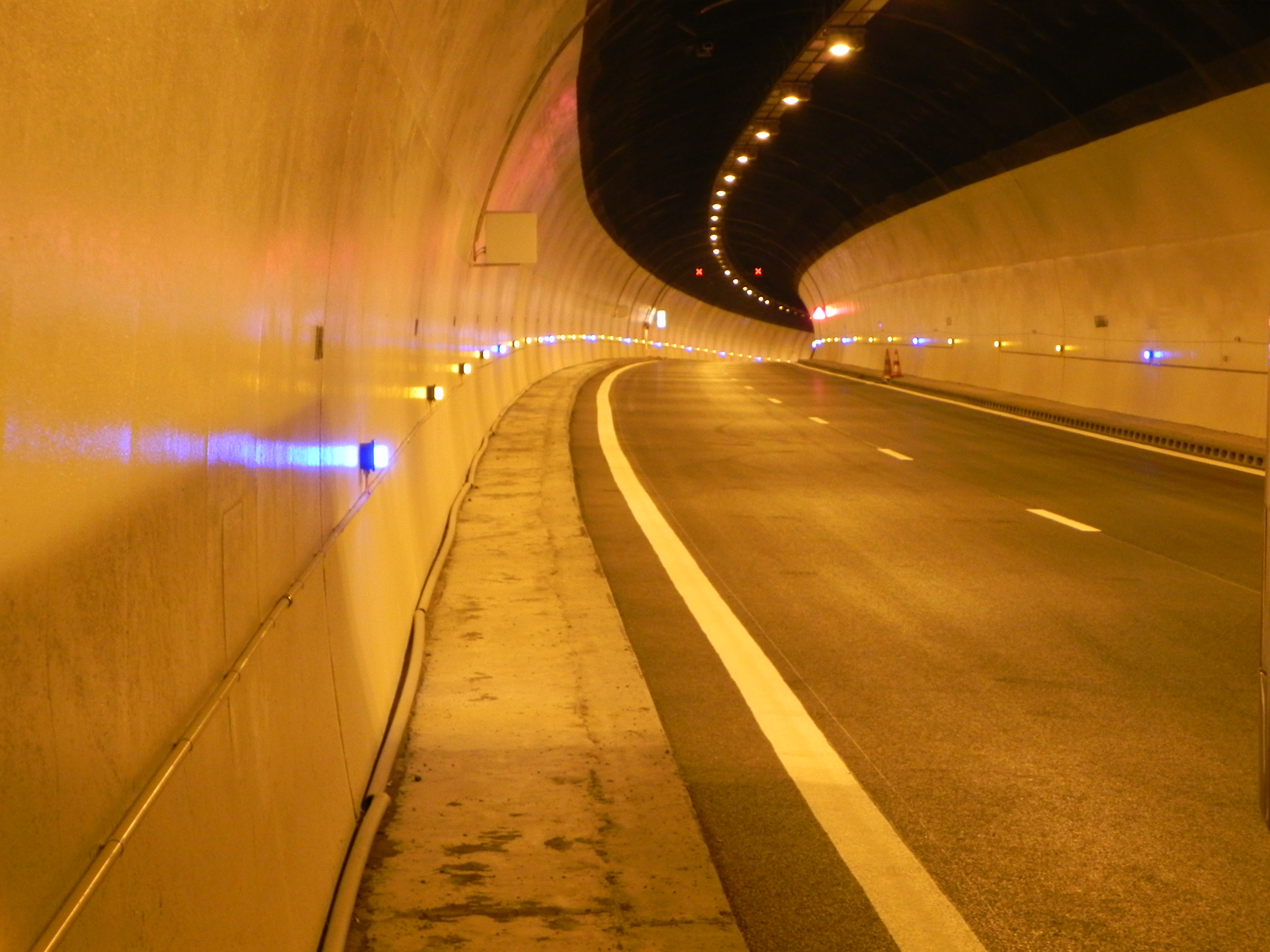
Figure 2: Example of interior zone lighting: Ponsérand tunnel (France)
Interior zone lighting
Once drivers have adapted to the lower luminance levels in the tunnel, sufficient lighting is needed in the interior zone for safe passage. Luminaires in the interior zone are therefore spaced at regular intervals, throughout the rest of the tunnel. Daytime and night-time levels of interior zone lighting are controlled by a photoelectric cell.
The design of a lighting installation should respect several criteria, notably those relating to the:
Several types of installations are possible; the most common are symmetrical lighting and counter-beam lighting.
Symetrical lighting
In symmetrical lighting systems, light is distributed symmetrically with respect to a plane perpendicular to the axis of the tunnel. An equal amount of light is sent towards each end of the tunnel. This system is generally used in the interior zone. It may be used in the entrance zone for tunnels which have a slow approach speed or where there is not enough room to install lighting fixtures above the carriageway.
Counterbeam lighting
Counterbeam systems project light in the direction of motorists, in conditions that avoid dazzling. This type of system, which should be fitted above the carriageway and facing the traffic flow, uses the photometric properties of the pavement (bness and specularity). It is suitable for use in entrance zones if there is sufficient room to install light fixtures above the carriageway. It has advantages in terms of investment costs and operation costs, especially when the approach speed is relatively high (>70 km/h).
In addition to the type of lighting system, attention should also be paid to coatings on the side walls of tunnels which can affect the overall efficiency of the chosen system. For symmetrical lighting, wall coatings should preferable be light coloured. In the case of counterbeam systems, darker, but more specular coatings are preferred.
Depending on the characteristics of the tunnel and the type of lighting system, the light fittings may be installed in one or more rows, above the road or at the top of the side walls.
The term « ventilation » combines several functions: pollution ventilation, smoke extraction, and sometimes ventilation for environmental protection purposes.
As explained on the page "Ventilation principles", in certain cases, ventilation in road tunnels can be achieved without the need of mechanical equipment (natural ventilation). However, in most of the tunnels with a length above some hundred meters, mechanical ventilation is unavoidable, which requires the design of a tunnel ventilation system (see the page on "Design and dimensioning").
The characteristics of the ventilation equipment to be installed strongly depend on the type of ventilation system for normal operation and fire scenarios.
Longitudinal ventilation systems utilize the tunnel tube as the “duct”. With the help of an air-jet placed in the tunnel air column, the flow resistance can be overcome by converting the jet momentum into static pressure.
The air jets can be placed at the tunnel entrance (Saccardo), blowing outside air into the tunnel or as ducted fans (usually called jetfans) along the tunnel, each one accelerating part of the tunnel air flow. Jetfans can work in both tunnel directions. (see section IV.2 “Longitudinal ventilation” of the PIARC report 1996 05.02 “Road Tunnels: Emissions, Environment, Ventilation”).
When a fan is installed into a tunnel a considerable decrease in the thrust occurs when the unit is close to the soffit or wall of the tunnel or in a niche. In those cases, it is recommended to use additional devices in order to maximize the installation factor. Examples are deflectors, inclined metal sheets, inclined silencers or nozzles. Section 4.4.4 "Ventilation" of the PIARC report 2017 R02 "Road Tunnel Operations: first steps towards a sustainable approach" provides some examples of efficiency improvement in longitudinal ventilation.
In some countries, air filtration systems have been put in place to mitigate the impact of vehicle emissions on ambient. Section 4.4.5 "Air cleaning" of the PIARC report 2017 R02 "Road Tunnel Operations: first steps towards a sustainable approach" provides some examples and approaches in different countries.
Jetfans operating in a tunnel can generate high noise levels, and can have adverse effects on speech transmission between people in the tunnel. This may become a safety issue when the noise level prevents the tunnel users from understanding what they are asked to do or when it makes it difficult for the firemen to communicate with each other. Therefore, some care must be taken in the assessment of sound emission by the jetfans.
Transverse ventilation uses ducts that run parallel to the tunnel. Two kinds of ducts are typically utilised:
Extraction for smoke control is usually concentrated to a zone smaller than the length of the duct by the addition of motorized, remotely controlled dampers, also known as “point extraction”. The fans serving the ducts are often located in ventilation plants close to the tunnel portals or shafts; however, many variations can exist.
The extraction fans must be sized to ensure the required extraction airflow rates for all fire locations in the tunnel. In the past, extract ducts were typically connected to the tunnel with a number of small, evenly spaced open vents. This concept has since evolved by replacing the small, open vents with larger vents equipped with remotely controlled motorised dampers and spaced further apart. The use of thermal fuses and panels has been assessed and found to have adverse effects: the effectiveness of the smoke control system using such thermal devices was found to be compromised by the untimely opening of some dampers and/or the opening of dampers in non-optimal locations.
The thermal resistance of the fans must ensure that the extraction of the hot smoke is possible with any configuration. Cables, junction boxes and all other non-protected parts of the ventilation system should have the same fire resistance as fans. For more details on fire resistance of other equipment, see section VII.5 "Fire resistance of equipment" of the 1999 PIARC report 05.05.B "Fire and Smoke Control in Road Tunnels". Additional information on maximum temperatures measured during the Memorial Tunnel and the Zwenberg Tunnel fire tests can also be found in this PIARC report 1999 05.05.
To fulfil their function, dampers must be able to withstand normal tunnel environmental conditions and to operate under emergency conditions.
Ventilation equipment should meet a number of specifications, including resistance to fire and acoustic performance. Chapter 4 "Ventilation" of Report 2006 05.16 and its appendices 12.3 "Jet Fan calculation procedure", 12.4. "Smoke dampers" and 12.6. "Sound impact of jet-fans" provide additional information on ventilation equipment for longitudinal and transverse systems.
Life cycle aspects need also to be accounted for in the design and selection of tunnel ventilation equipment. Additional information can be found in the PIARC report 2012 R14 "Life Cycle aspects of electrical road tunnel equipment".
In some cases, as for complex or urban tunnels, specific considerations need to be considered in the equipment requirements, as described in chapter 7 "Other equipment & operating facilities" of the PIARC report 2016 R19 "Road Tunnels: complex underground road networks".
Ventilation tests
Because the ventilation system plays a major role in tunnel safety, it is essential that it operates properly and effectively at all times. To achieve this goal, sets of tests have to be defined and adapted to specific tunnel specifications The primary objective of road tunnel ventilation system testing is twofold:
Three kinds of tests are usually performed in order to check the equipment and the safety objectives of the ventilation system:
It is generally impossible to perform integration tests with fires as large as the design fires. Most commonly, the main purpose of these tests is to train tunnel operators and members of the fire brigade.
The list of tests and corresponding timetables must be adapted to each particular tunnel, and depends on the installed equipment, traffic volume and degree of utilisation of the installations, and cover several aspects, including:
Chapter 8 "Operational responsibilities for emergencies" of the PIARC report 2007 05.16 "Systems and equipment for fire and smoke control" describes in more detail the appropriate ventilation tests for ventilation systems.
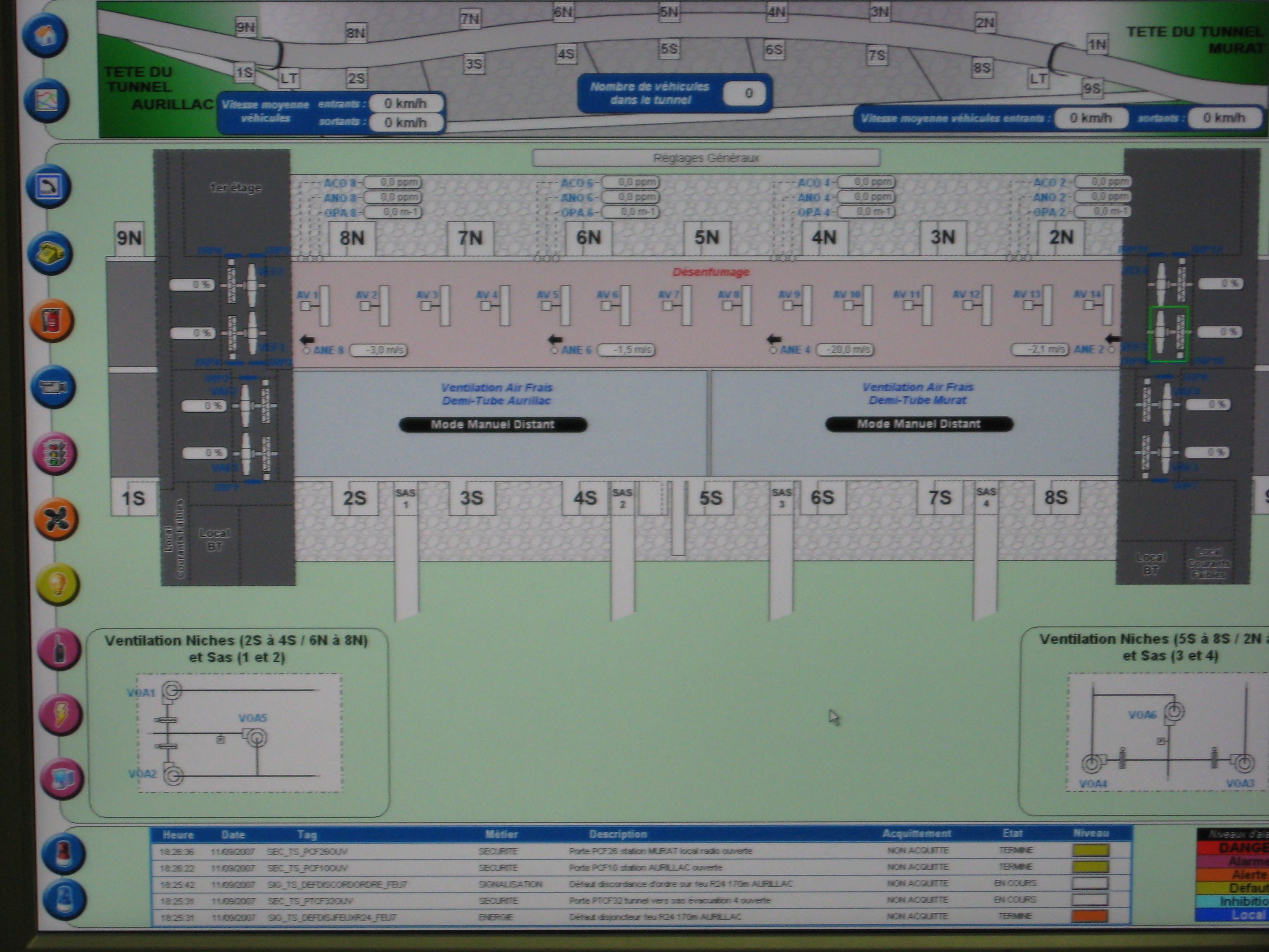
Figure 1: SCADA system operating ventilation in the Lioran tunnel (France)
Many devices are servo-controlled by sensors and operate automatically (e.g.lighting, ventilation.) according to pre-determined thresholds. Others are activated or deactivated depending on the operating conditions. It is thus useful for the operator to be able to remotely control them (such as signals, variable message signs, barriers, ventilation as fig. 1, lighting, pumps ...).
As the equipment may be operated very differently (continuously, occasionally, or very rarely), it is necessary for the operator to have information on the operational duration (hour used) of each item.
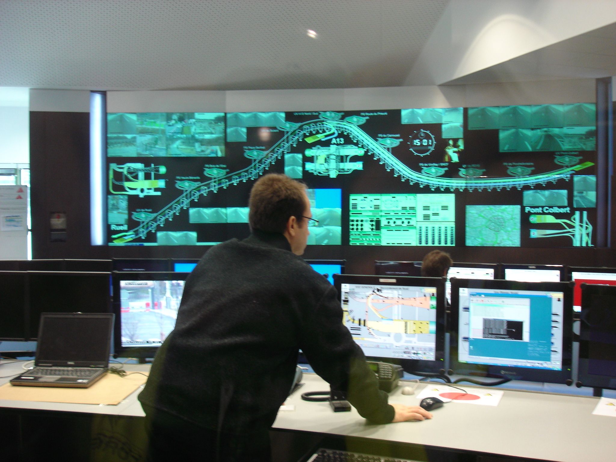
Figure 2: SCADA system in a tunnel control room
Several SCADA systems are available worldwide and their performance is being improved constantly. The systems installed in road tunnels of comparable characteristics are therefore rarely completely identical, even for the tunnels belonging to the same operator. Even so, the architectures follow certain rules that are widely prevalent:
With the development of internet and connected devices, SCADA are becoming increasingly vulnerable to cyber attacks. As they are the core of the safety process, efforts must be made to protecting them from this new threat.
To manage the traffic and provide users with more comfort, a large variety of equipment can be installed inside the tunnel. Signs and signals are some of the main devices available to the operator to perform this task.
For a given type of road, tunnels have the same signs and signals as in open air:
The means available to the operator to manage the traffic on the route where the tunnel is located and inside the tunnel include:
This equipment could be located inside the tunnel, but also at the entrance to the tunnel and (if possible) at a distance sufficient for the user to be able to be diverted to an alternative route, if necessary. The main problem with regard to signage within a tunnel relate to the geometrical characteristics which must be optimised. Increasing the cross section will lead to significant extra costs. In practice, a compromise must be found between the need for good visibility of the signs (which must be sufficiently large) and the space available.
The different safety devices available to tunnel users (emergency telephones, extinguishers, emergency exits...) require additional specific safety signage (see page Monitoring and Incident detection and Evacuation aids).
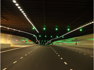
Fig 1. Example of dynamic lane allocation signs (Singapore)
Fixed signs may indicate the usual speed limit, that overtaking is prohibited or the distance to be respected between vehicles. Other fixed signage that is specific to the tunnel environment indicates the different safety facilities or devices available to tunnel users (such as, lay-bys, emergency stations with emergency telephones, extinguishers).
In the event of an accident or breakdown, dynamic signs may be used to communicate important information to the users and to manage traffic. Lane allocation signs, positioned above the carriageway indicate which lanes are open and may indicate to users that they need to merge either to the or . Dynamic speed limit signs can inform users of modified speed limits. Variable message signs can be used to inform tunnel users of the nature of the incident and indicate the appropriate behaviour to adopt (slow down, stay in lane, etc)
If a traffic incident involves a fire requiring the evacuation of users, in addition to evacuation messages displayed on VMS, specific signs indicate the evacuation route leading to emergency exits.
All signs should be designed and positioned so that they are clearly visible and easy to read. Signs should include a relatively short text or message so that they can be easily read by motorists. In practice, a compromise must be found between the need for good visibility of the signs (sufficiently large panels) and the space available.

Figure 1: Approach signs on the run up to a tunnel in Austria
Approach signs that provide a warning to drivers of the authorised vehicle height may be included into a height restriction device (Fig. 2).

Figure 2: Height restriction signs and barriers on the approach road to a tunnel in Austria
Signs located near tunnel portals mostly indicate certain restrictions/mandatory behaviour with regard to the use of the tunnel.
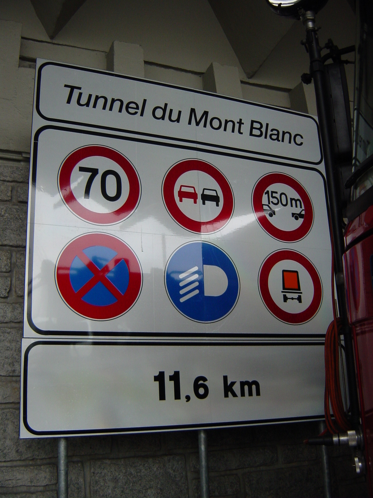
Fig.1: Regulatory signs grouped together onto a single sign at the Mont Blanc tunnel portal
Typically, regulatory signs at portals are used to indicate:
These regulatory signs can sometimes be grouped onto a single sign as given in Fig. 1.
Certain countries have a specific « tunnel » sign to which some of the above-mentioned information is added.
Information signs are usually also located near the tunnel portal, providing:
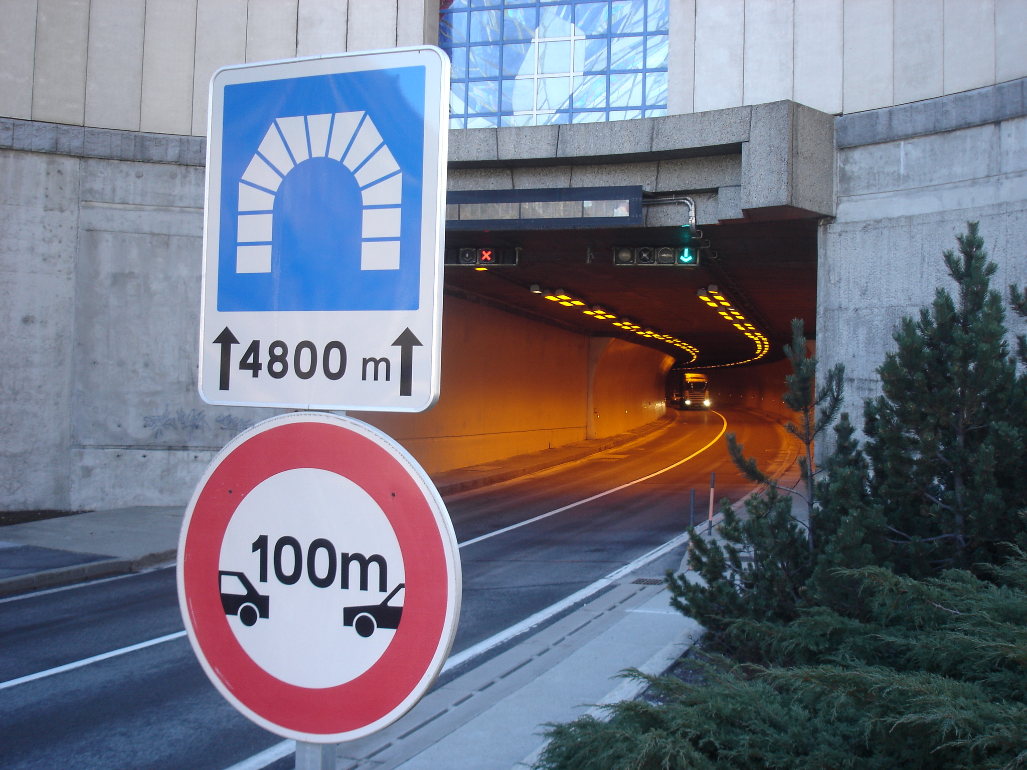
Figure 2: Signs at a portal showing the length of the tunnel and the distance to be kept between vehicles
For tunnels with a height limit that is lower than that of the access road, there is also a sign indicating the maximum authorised height. This sign may also be accompanied by a physical obstacle designed to limit the risk of over-height vehicles hitting tunnel equipment.
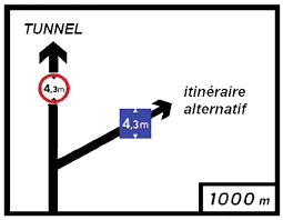
Figure 1: Sign indicating that the tunnel is prohibited to vehicles with a height over 4.3 metres and that an alternative route must be taken (France).
If they are restricted to certain categories of vehicles (over-sized vehicles, dangerous goods vehicles), alternative routes must be available and clearly indicated as shown in the example below.
If a tunnel is completely closed, due to an accident, road works etc, all users must be informed of the various alternative routes. It is necessary to provide information to users as far upstream as possible, before the relative points of choice, which are sometimes located at a considerable distance from the tunnel. If the tunnel is part of an urban network, other signage means can be used to facilitate the management of diverted traffic (e.g. variable message signs).
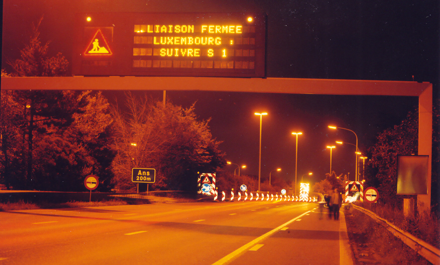
Figure 2: Variable message sign indicating a tunnel closure due to road works and the alternative route to be taken (Belgium)
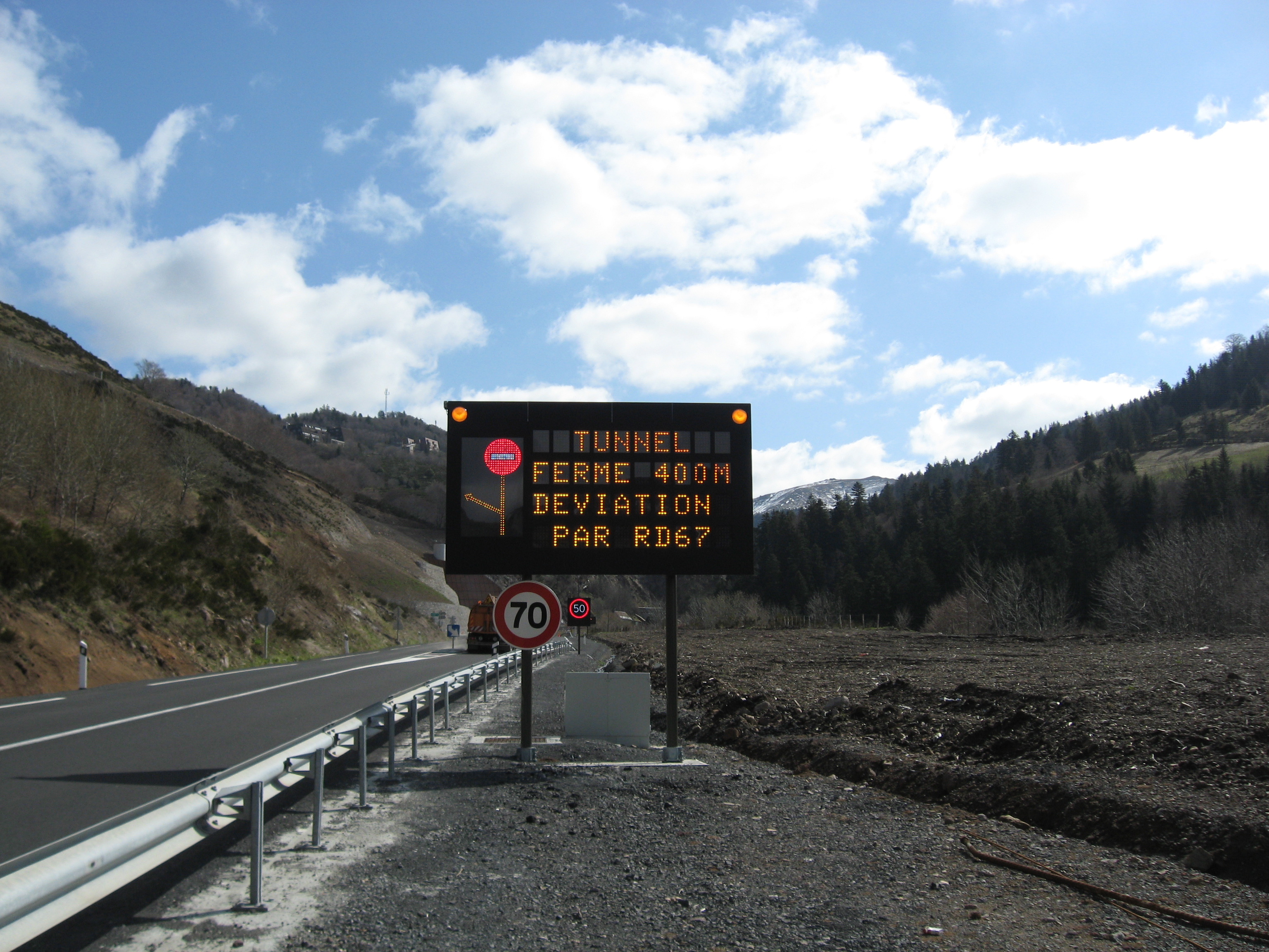
Figure 3: Sign indicating the closure of the Lioran tunnel and the alternative route (France)
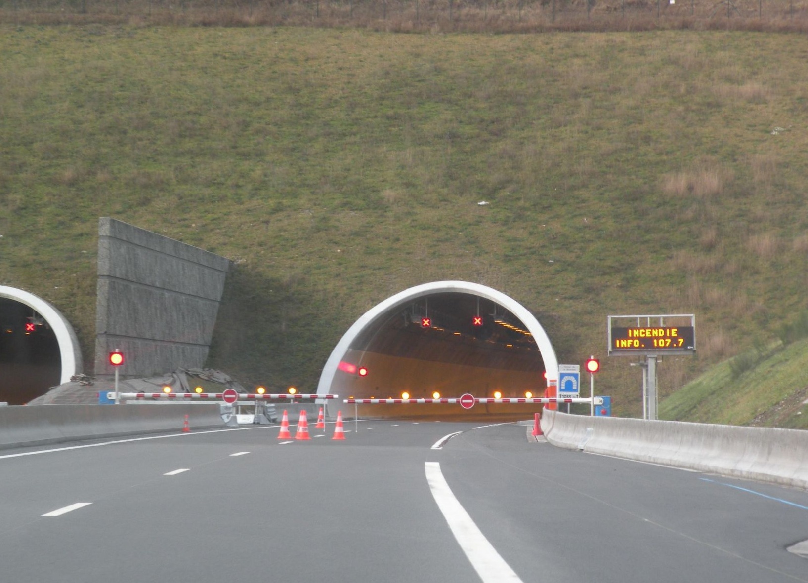
Figure 1: A double closure barrier, used in combination with a stop signal and a variable message sign, (France)
When a serious event (accident, fire, etc.) occurs in a tunnel, it must be possible to prevent users from entering as they risk encountering a potentially dangerous situation.
Devices are therefore used to warn users who are outside that the tunnel is closed and/or prevent them from entering.
In many countries, experience shows that if the tunnel is closed simply by means of a stop signal placed in front of the entrance, it is not always effective.
Therefore, this stop signal is often combined with barriers and variable message signs, allowing the users to be informed of the reasons for closure (Fig.1)
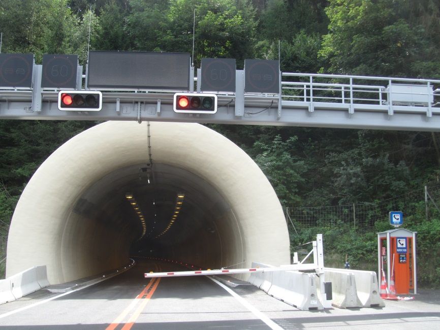
Figure 2: Example of a single tunnel closure barrier used in combination with stop signals (Austria)
The tunnel closure device can be activated from the control-command centre or automatically in tunnels that are not monitored continuously. Some road authorities also mandate that a ground responder has to be deployed at the tunnel entrance before the barrier can be safely lowered.
The closure device is meant for use in emergency situations but it can also be used in other situations, particularly during scheduled closures for maintenance interventions.
In normal operating mode, the monitoring of a tunnel usually consists of a visual monitoring of traffic by means of video surveillance cameras (CCTV).
In the event of an incident in the tunnel, the alarm can be raised by video surveillance or by more specific means such as:
The ‘’quality” of the information provided by each of these devices is linked to the very nature of the device (an emergency call station makes it possible to locate and establish contact with users, whereas notification of the removal of a fire extinguisher may indicate the start of a fire, but does not provide more detailed information).
These devices therefore do not provide the operator with the same degree or ‘’quality” of information, although they provide an initial alert. The operator may use additional equipment to verify the alert or to obtain further information.
A traffic surveillance system is often installed when the level of traffic is very dense in a tunnel. Usually, a video-surveillance system is used, supplemented sometimes with counting devices. A video-surveillance installation provides the operator with important information in order to make decisions about controlling the traffic conditions in the tunnel in real time. In case of degraded or emergency operation, it allows the concerned incident zone to be viewed so that required actions may be rapidly evaluated.
Video-surveillance is thus a very valuable tool for the operator because it enables continuous incident monitoring inside the tunnel and rapid reactions when necessary.
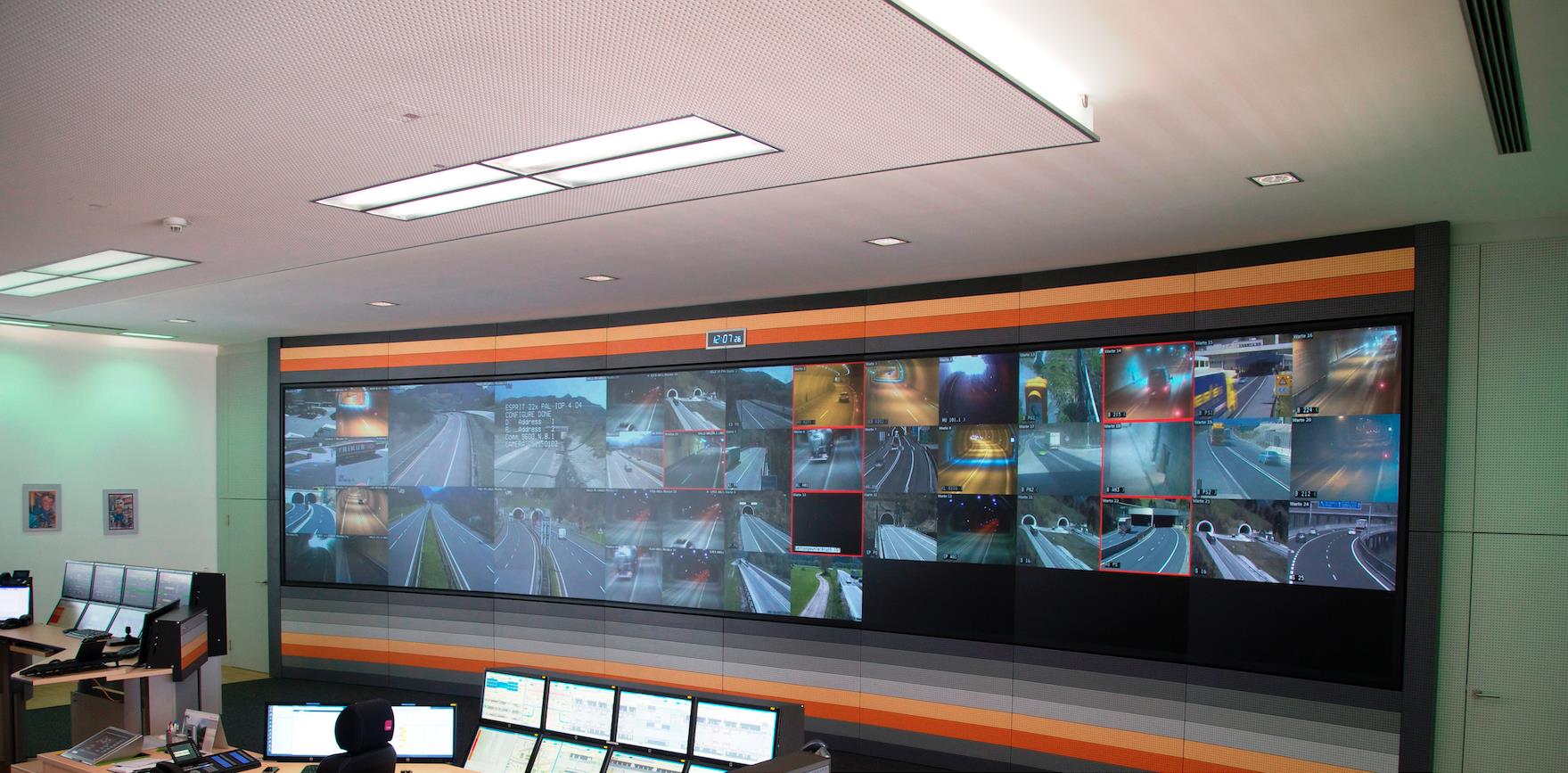
Figure 1: Example of a tunnel CCTV system
However, in order to make full use of a video-surveillance installation, it is essential to maintain a human presence, if possible continuously, at the control-command centre.
Video-surveillance is generally quite simple in its design. Cameras placed at regular intervals in the tunnel provide a complete coverage of the tunnel and its surroundings. The images are then grouped and transmitted to the control-command centre of the tunnel by networks that may or may not be dedicated to this function. The images are then received and viewed on the displays (Fig. 1).
CCTV systems can also be relayed to automatic incident detection systems (to detect smoke, fire, accidents, traffic jams or intrusions for example). AID systems are especially useful for long tunnels, where it is difficult for the operator to observe the entire tunnel even with a wall of screens.
E
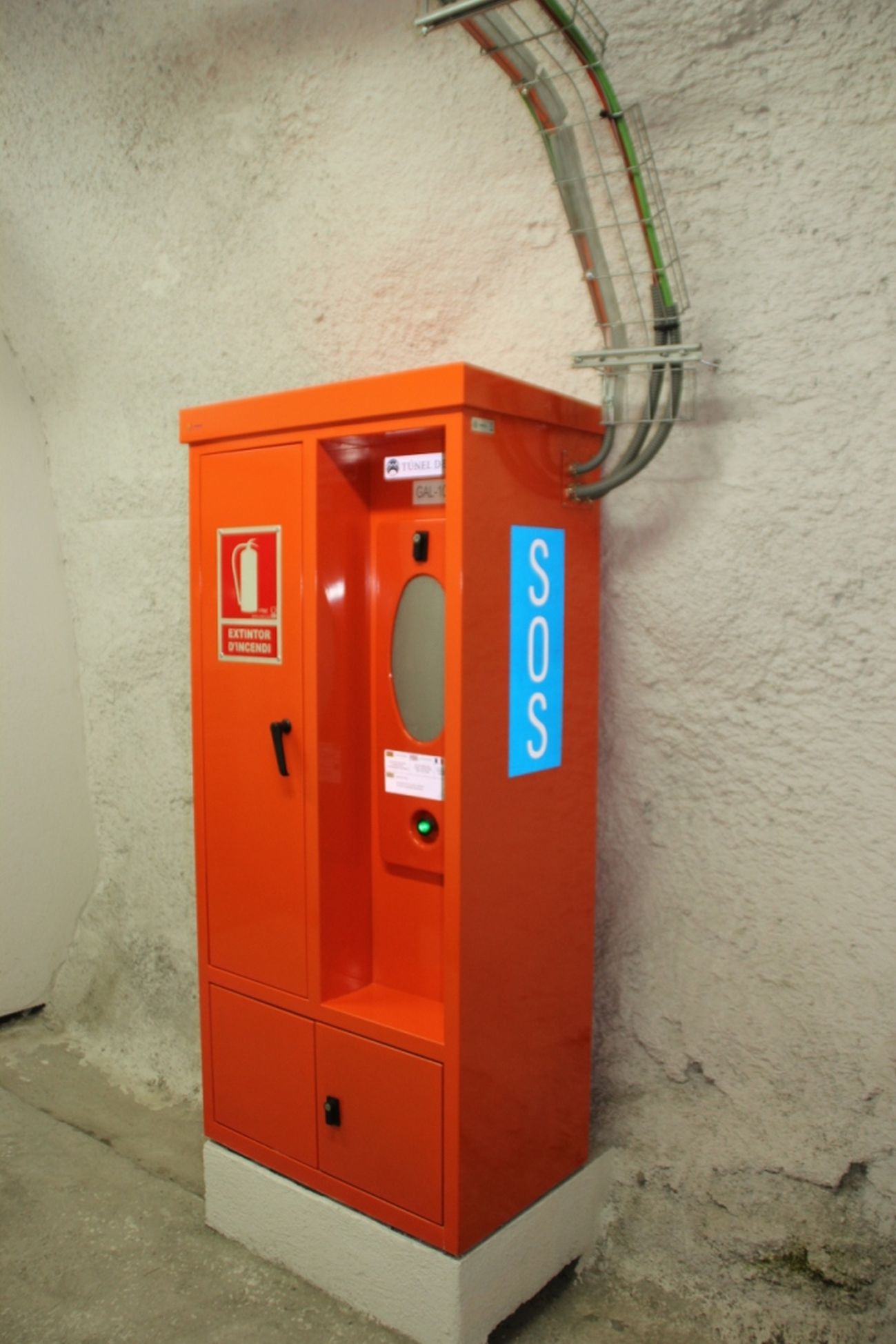
Figure 1: Emergency telephone in a road tunnel (Spain)
Each emergency telephone is given a unique numeral ID which is displayed onscreen when the user/victim picks up the receiver, which allows the control-centre personnel to quickly locate the source of the call. Likewise, the control-command centre can also ring the emergency telephone and provide the user/victim with advisory instructions.
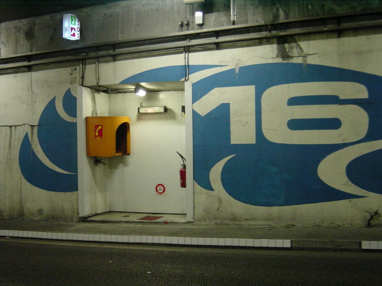
Figure 2: Emergency telephone in a safety recess (France)
These emergency telephones are installed at fixed intervals on boxes or in emergency stations of different types. The distance between two emergency telephones is often specified by regulations and therefore varies from one country to another.
The structure of this device is quite simple. The emergency telephones in the tunnel are connected to a centre that receives the calls made from the tunnel. Usually, this centre is located in the control-command centre of the tunnel and sometimes in the premises of police services under whose jurisdiction the tunnel is placed.
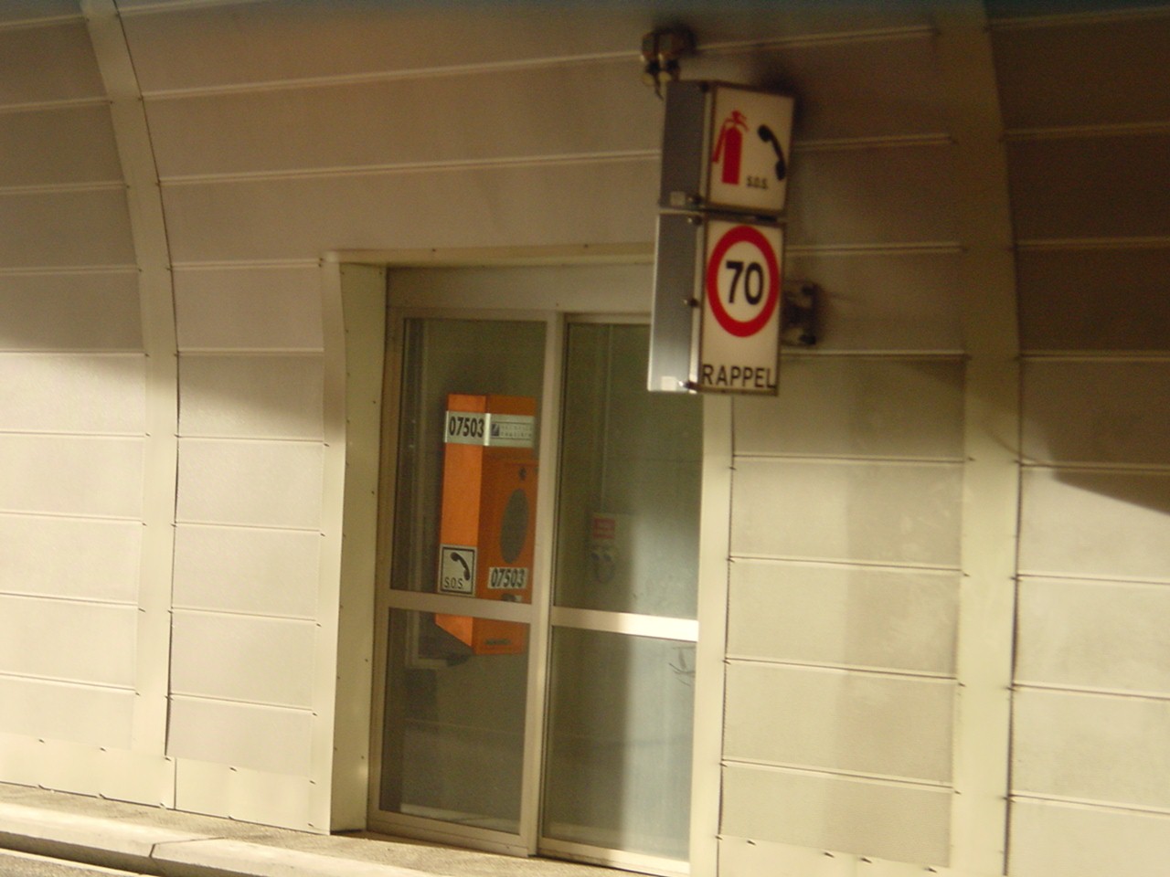
Figure 3: Emergency telephone in an emergency station (France)
As mentioned above, the user has access to several devices for use in a tunnel, particularly in emergencies. These devices include fire extinguishers, emergency stations (containing emergency telephones and fire extinguishers) and emergency exit doors.
Automatic alarms are triggered when emergency systems such as doors and/or extinguishers are used. For fire extinguishers, it is the action of removing the equipment from its support that triggers the alarm. For emergency station and emergency exit doors, it is the opening of the door or the detection of a presence in the exit that is the trigger.
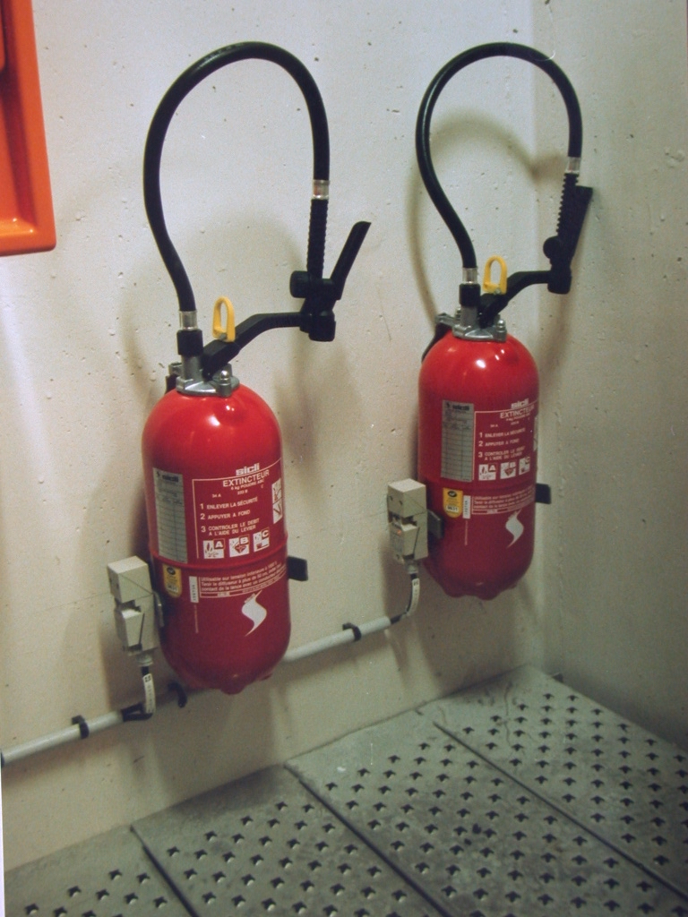
Fig 1 : Extinguishers with sensors at the
The opening of a door or removal of an extinguisher will often result in automated actions being triggered. For instance, a CCTV camera may be programmed to automatically turn to the door that was opened to aid a more efficient response by the operator. It is essential for the tunnel operator to be informed as early as possible when a user operates one of these devices, in order to take adequate actions. Where national standards require the tunnel to be monitored by full time Operators, then these devices will be monitored using switches. These switches are connected to the plant monitoring SCADA system. In the event that a door is opened, or an extinguisher removed, then the plant monitoring system will raise an alarm to the operator located in the control room.
Manual call points (also named Alarm pushbuttons) allow a user to send an alarm to the control-command centre in case of an incident in a tunnel. These manual call points are not very expensive so they can be installed at frequent intervals, typically every 25m to 50m.
These devices are not often activated by tunnel users because users tend to prefer using emergency call stations (emergency telephones) that provide real-time audio conversations with an operator. Manual call points do not provide real-time feed back to the user.
Most road tunnels that have a manned control room are equipped with a Closed-Circuit TV (CCTV) system (refer to the page on CCTV system).The CCTV images are usually displayed on a video wall in the control centre. The CCTV system allows operators to monitor the tunnel to identify incidents. It can often be difficult for the operator to monitor more than a few displays simultaneously because of the large quantity of images available and with other duties that the operator has to perform.
To ensure that incidents, such as slow moving or stationary traffic, are detected early, tunnel operators are increasingly installing Automatic Incident Detection (AID) systems. In some countries, the use of such equipment is mandatory for certain types of tunnels.
Two main types of AID systems are available for use in road tunnels, Video-based and Radar based. The video-based systems (V-AID) generally use fixed CCTV cameras to provide full coverage of the roads and walkways. The video-based system provides useful time-stamped video images of incidents which can help in assessing why incidents occurred and who or what may be responsible for causing the incident. Fixed camera V-AID systems are also available with Infrared cameras so that the system can provide video images in low light and smoke-filled conditions. Radar based systems cover a greater area than one fixed camera, so require less infrastructure in the tunnel. The output from a radar system is a grey-scale image that works in all environmental conditions in a tunnel.
V-AID systems are normally based on computer-based analysis of video image streams generated from cameras set up to view tunnel traffic. The video analysis compares each frame from the video camera with the previous frame and checks for differences outside what is considered to be ‘normal’ behaviour. A number of algorithms are available from the VAID system which can detect a range of incidents, including:
Each type of event to be detected is associated with a false alarm frequency. Increasing the number of events to detect will therefore increase the occurrence of false alarms and thus reduce the reliability of the AID system.
It is therefore very important to limit the type of events to be detected to those that are strictly necessary in order to make the system as reliable as possible, to limit the frequency of false alarms and to reduce the cases of non-detection of events.
Since serious vehicle fires normally develop after traffic has stopped (e.g. following an accident), it follows that a 'stopped vehicle' alarm from an AID system can be expected to precede alarms triggered by other systems, such as temperature and smoke detectors. This early warning provided by AID systems provides time for tunnel operators to confirm the nature and location of the incident, and to allow more effective intervention. This may be through the choice of optimal ventilation configuration, prevention of secondary accidents through operational measures, rapid warning to motorists upstream of the incident, and tunnel closure. It also gives operators the opportunity to call the emergency services, display warning or information messages on variable message signs, broadcast messages on public address and the radio voice break-in systems, call to breakdown lorries, advice to exit the tunnel, etc.
Video smoke detection systems are described in Section 6.3.3 "Currently Used Methods" of report 05.16.B 2006.
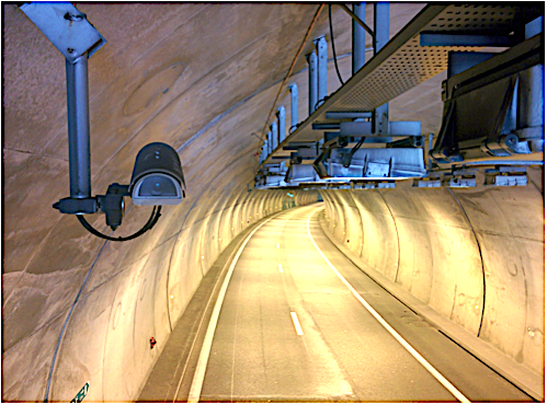
Fig. 1: Camera equipped with AID (photo Credit CETU)
Video-based AID systems can also provide real-time information on the traffic flow, volume and speed. They can record pictures at the origin of the incident (Fig. 1) and can interact with other systems such as the Supervisory Control and Data Acquisition (SCADA) system. Video-based AID systems normally include IP (Internet Protocol) cameras, a video image processing system processing images from one or several cameras. The video images may be fed back to monitors or computer displays in the control centre. The V-AID cameras may also be monitored by the video management system, comprising of redundant servers, providing video and other functions (mass recording of video and incidents from the AID system, collecting and storing real-time traffic data and traffic events, interfacing with the tunnel SCADA system), network equipment and communications lines (optical fibres, coaxial and Unshielded Twisted Pair cables).
Recent technology in video processing allows the V-AID algorithms to be run on the cameras (or near the cameras), rather than on a central server. This approach means that only video incident files of detected incidents are transmitted to the SCADA system when there is an incident, rather than constantly transmitting (streaming) real time video from all cameras. This reduces the transmission load on the tunnel communications network
The design of AID systems in tunnels should be undertaken with due account of the following issues:
The 2009 Routes/Roads article "Fire Detection Systems in Road Tunnels - Lessons Learnt from the International Research Project"concluded that "to deal with obstructions, most sensor manufacturers recommend two sensors covering the same area from different angles, such as from both directions within a tunnel". Multiple cameras may also be required for redundancy purposes, in case of camera failure. Typically, the camera fields of view are designed to overlap, such that failure of any one camera can be compensated through the images from neighbouring cameras.
Section IV.2.1. "Incident Detection Devices" of report 05.15.B 2004 suggests that camera locations can vary from 30 to 150 meters if they are used for automatic incident detection. More recent recommendations from the V-AID manufacturers is that the cameras should cover a distance of no more than twenty times its mounting height. Therefore, if a camera is mounted at 5 m above the road then it should be able to provide reasonably accurate detection of incidents for a distance of 100m. However, as mentioned above, to ensure redundancy coverage in the event of a camera failure, then V-AID cameras should be installed every 50 to 80 m.
The performance of an AID system depends to a great extent on successful commissioning and calibration prior to deployment. Experience shows that the decision on detection time for the system has an important influence on the systems detection accuracy and the amount of false alarms registered. Experience from existing tunnel installations indicates that such commissioning and calibration can take several months under operation to undertake.
Fire and smoke detectors are always an integral part of a control loop which comprises sensors, alarm triggering equipment, transmission cabling, evaluation units, etc., and which together are generally referred to as a fire alarm system.
Fire and smoke alarm systems in road tunnels are designed to detect fires and smoke production as fast as possible so that safety equipment and procedures can be activated without delay. Their main objectives should be to:
Fire detection principles are based on perceived parameters i.e. heat, smoke, radiation and production of typical chemical substances. Therefore, fire detection sensors include:
Each of these detectors has their own specific application domain, related to its response time, robustness, reliability, etc.
Recently video AID systems have proven to be very efficient and fast in detecting fires. They detect incidents and any object or vehicle which does not conform to the normal expected traffic stream. The cameras can be automatically turned towards the incident scene, which enables the operator to discover the very early start of a fire.
Fire/smoke detection systems are described in Section 6.3 "Fire detection" of the report 2006 05.16.B.
Generally speaking, fire detectors in road tunnels must be designed to withstand the following environmental conditions: air velocities up to 10 m/s, reduced visibility resulting from diesel exhaust fumes and abrasive wear stemming from tires and the road surface, increased and short-term fluctuating concentrations of pollutants (carbon monoxide (CO), carbon dioxide (CO2), nitrogen oxides and hydrocarbons), changing headlight intensities, engine heat and hot fumes, vehicle exhaust gases, electromagnetic interferences, mixed vehicular traffic (i.e., cars, small lorries, heavy load lorries, buses and tankers) that will result in varying degrees of tunnel cross section obstruction.
It cannot be stressed enough that they must have a high degree of fail-safe operation and be able to determine the location of the fire as precisely as possible. It is advisable that fire detection systems possess a certain level of intelligence in order to avoid false alarms, as to rectify them could entail significant expenses and even worse, may eventually discourage the operators from paying attention to the alarms.
Furthermore, it is imperative that the fire detection/alarm installation is reasonably priced, has low operating costs and is simple to maintain: refer Section 6.3 "Fire detection" of the report 2006 05.16.B.
The following parameters for automatic fire detectors are specified in national and international codes and standards : maximum time for a fire to be detected, determination of the fire location, minimum fire load to be detected, approved detection methods, assembly points for fire alarms, details pertaining to which tunnels should be provided with automatic fire alarm installations (e.g. length of tunnel, tunnels with mechanical ventilation, tunnels that are not permanently monitored by personnel, short tunnels with particularly high traffic densities).
A list of detailed reference material regarding fire detector parameters are described in codes and can be found in Section 10 "References" of the report 2006 05.16.B.
The efficiency of fire detection is not only based on the type of devices (temperature, light beam extinction, ionisation, etc.), but also on the detection strategy which has been developed, which includes the number of sensors and their level of surveillance in the tunnel.
Automatic incident detection, analysis of video images including AID systems, closed-circuit television (CCTV) observation, equipment such as fire extinguishers which activate alarms by the removal, as well as the emergency telephones are generally good means to raise an alarm.
Many detectors in use are based on heat and on the rate of temperature rise. When well calibrated, this type of system generates only few false alarms, but may have a slow reaction rate. Detectors based on smoke obscuration give early signals but suffer more false alarms because of smoke exhaust from diesel vehicles: refer to Section VI.3.1 "Fire detection" of report 05.05.B 1999.
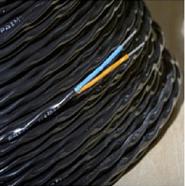
Figure 1: Linear temperature sensor
Tunnel operators have two means of directly communicating with users:
Broadcasting messages on FM frequencies is obviously only possible if the tunnel is equipped with a radio communication system. When such a system exists, it enables a limited number of frequencies to be retransmitted and the user’s car radio must be switched on. One of the benefits of this system is that information directly reaches the user in his/ her vehicle.
Broadcasting messages through loudspeakers is also an efficient means of communication, as long as they are clearly audible. Adjusting the system to reach a satisfactory level of performance, and notably to prevent reverberation, can be quite tricky.
This chapter is split into two parts:
A tunnel is an enclosed structure that usually does not permit the natural transmission of radio waves to travel very far into the tunnel. Since vehicle radios are a useful means of allowing tunnel operators to broadcast emergency messages to tunnel users, we must therefore provide a means to propagate radio signals through the tunnel.
This re-broadcast of radio stations is provided through the radio re-broadcast system using transmission equipment and a coaxial cable running through the tunnel. The coaxial cable leaks radio waves and is referred to as the “leaky feeder”.
The radio system is primarily used to allow emergency services to use their radios in the tunnel. It is also possible to install specific equipment that allows the retransmission of the required local and national radio frequencies into the tunnel.
To be able to broadcast emergency messages to vehicles on the radio frequencies, operators must interrupt the normal broadcast of radio stations, break into the frequencies and broadcast their own emergency message. This is called Voice Break-In, VBI.
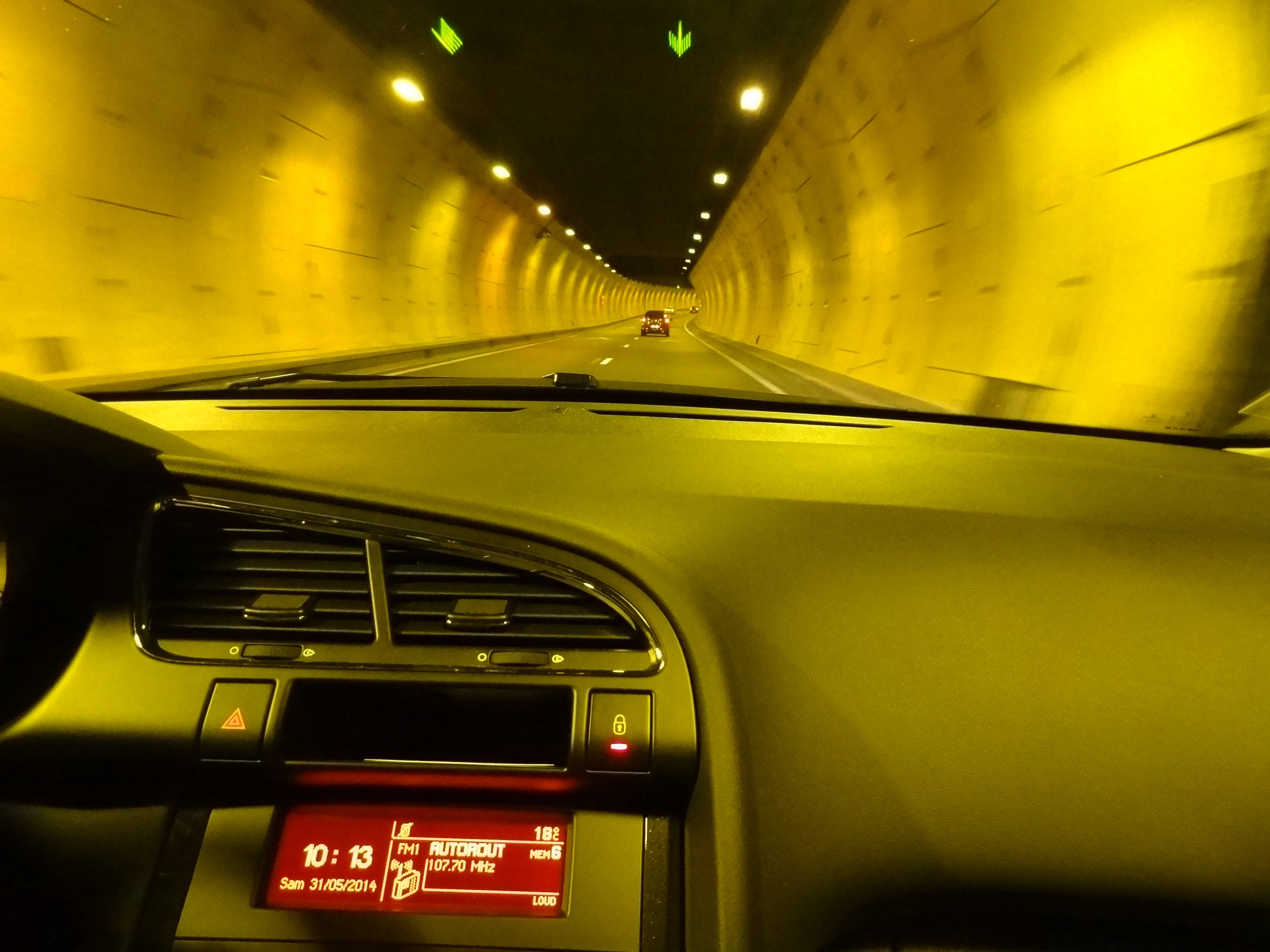
Fig 1: Voice break-in system used via vehicle radios
When needed during incidents, radio broadcasts are interrupted and safety messages are broadcast to tunnel users by the operator. These messages may be pre-recorded or live broadcasts. Text messages may also be transmitted to users’ radios using the Radio Data System.
These VBI messages will be transmitted in coordination with the public address system, if installed, such that PA messages are not broadcast at the same time as the VBI radio messages.
A radio-retransmission installation in a tunnel is essentially composed of:
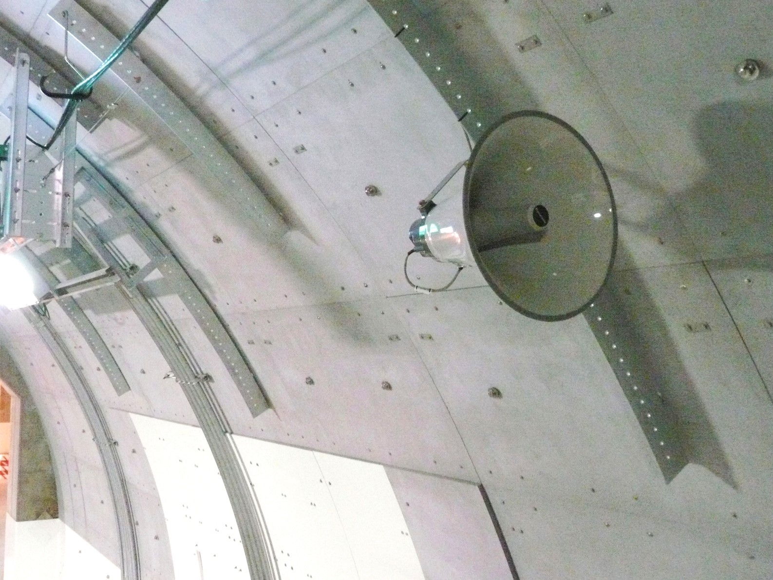
Figure 1: Loudspeaker installed in the Yamate tunnel (Japan)
These systems are explained in more detail in PIARC report 2016R06EN: “Improving safety in road tunnels through real time communication with users” and in the appendix to this report which provides the results of an international survey on the use of loud speaker public address systems.
In certain situations (notably in the event of fire), users will take the decision to evacuate the tunnel. This decision may be spontaneous or may follow evacuation instructions provided by the tunnel operator. More often than not, this evacuation phase will occur before operator personnel or external rescue services have arrived on site.
In addition to signage that helps users to identify emergency exits, two other means of guidance are implemented to help users reach the nearest exit:
This chapter is divided into four pages:
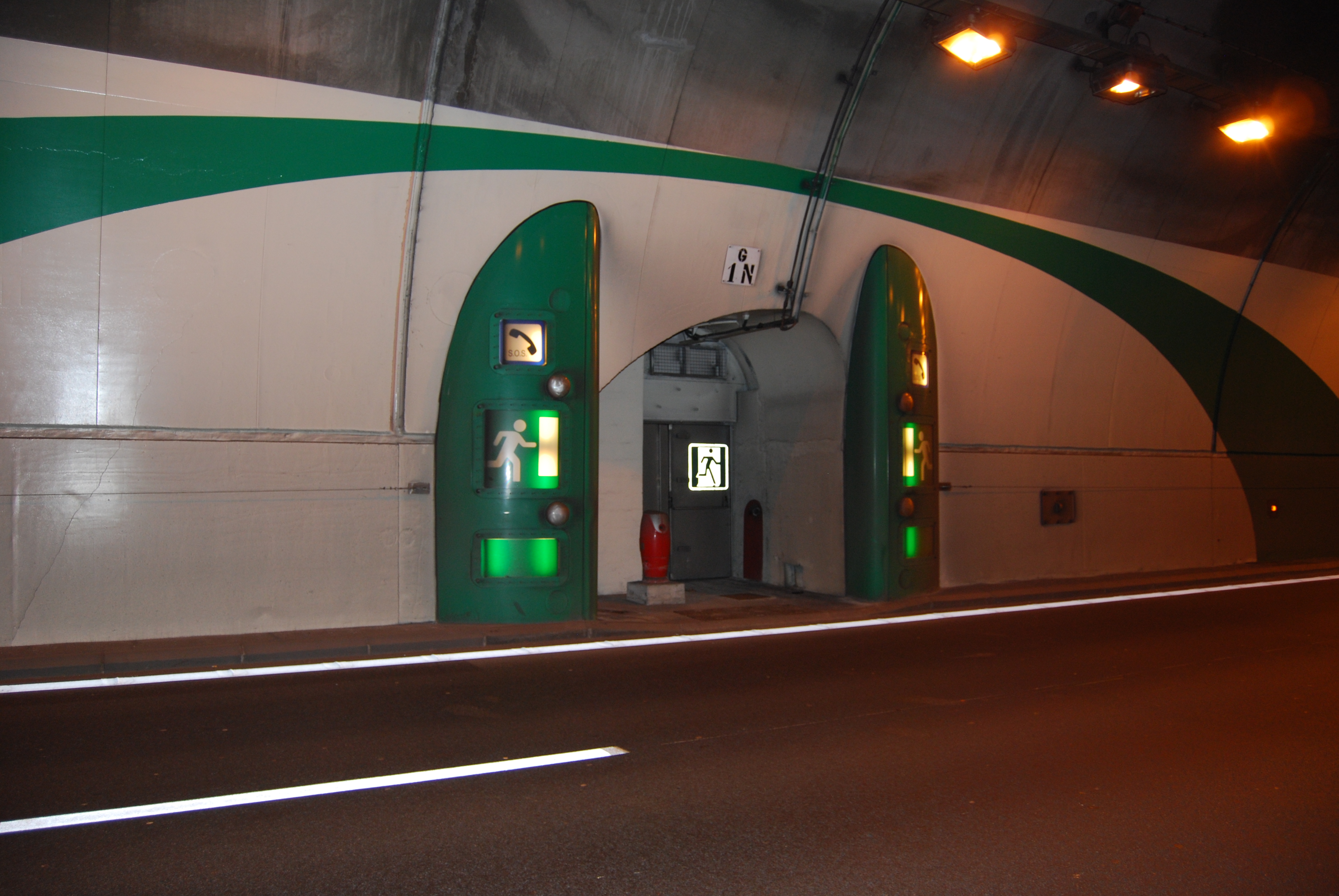
Fig.1. Example of signs indicating the location of an emergency exit (Les Monts, France)
It is usually obligatory to install distance markers to the emergency exits for pedestrians. Standardised panels should be used for this purpose. They are installed in pairs, parallel to the road direction, at intervals of about twenty meters (see Fig 2).
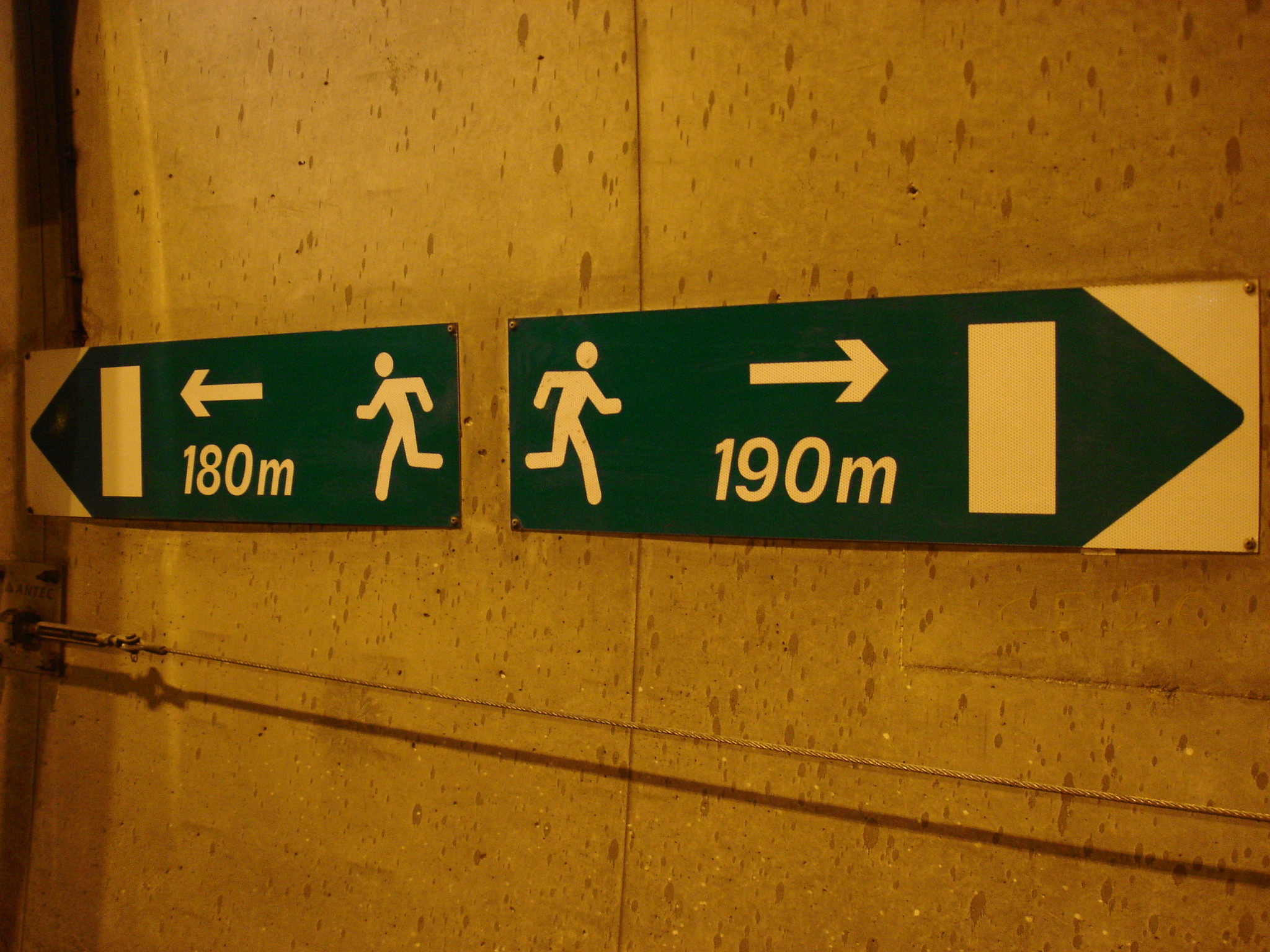
Fig. 2. Example of signs indicating the distance to the nearest emergency exit (Condamine Tunnel, France)
In the majority of tunnels, there is a lighting system that provides a lighting level in accordance with national and international road tunnel lighting standards for ‘normal’ tunnel operation. The lighting system will also provide additional ‘emergency’ lighting in the tunnel during periods where the mains power supply has failed for a limited period. The emergency lighting (approximately 10% of the ‘normal’ lighting level) will be powered by an Uninterruptible Power Supply (UPS). The UPS is a battery backed system.
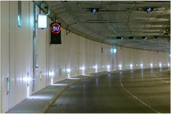
Fig. 1 : Evacuation lighting (Credit photo OFROU)
In twin-tube tunnels, links between the tubes known as “cross-bores” or “cross-passages” enable users to evacuate to a place of safety. Very often, these cross-passages are only accessible to pedestrians and the geometrical characteristics of cross-passage doors must facilitate pedestrian access.
Some tunnels also have cross-passages that are accessible to emergency service vehicles.
The characteristics of cross-passage doors (reaction and resistance to fire, air tightness, thermal insulation, etc.) must be adapted to regulations in force and must be consistent with the fire resistance performance of the structure surrounding the door.
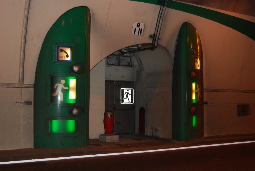
Fig.1: Example of cross-bore door and signs (Les Monts tunnel, France).
Signs must be used to indicate the presence of cross-passage doors. They are usually illuminated for improved visibility and are located next to each door in the part of the tunnel open to traffic. They must be visible from both sides of the door: upstream and downstream.
Additional signage may also be used, such as:
Specific measures must be taken to ensure that in the event of fire, the smoke present in one tube does not spread to the other tube (airlock at each end of the cross-passage, which may be equipped with an over-pressure system).
The afore-mentioned characteristics can also apply to other evacuation facilities: passages with a direct link to the open air, links to an escape gallery or passages leading to an emergency shelter.
Various public address systems exist to help facilitate the evacuation of users through emergency exits, including sound beacons which can be found in certain tunnels.
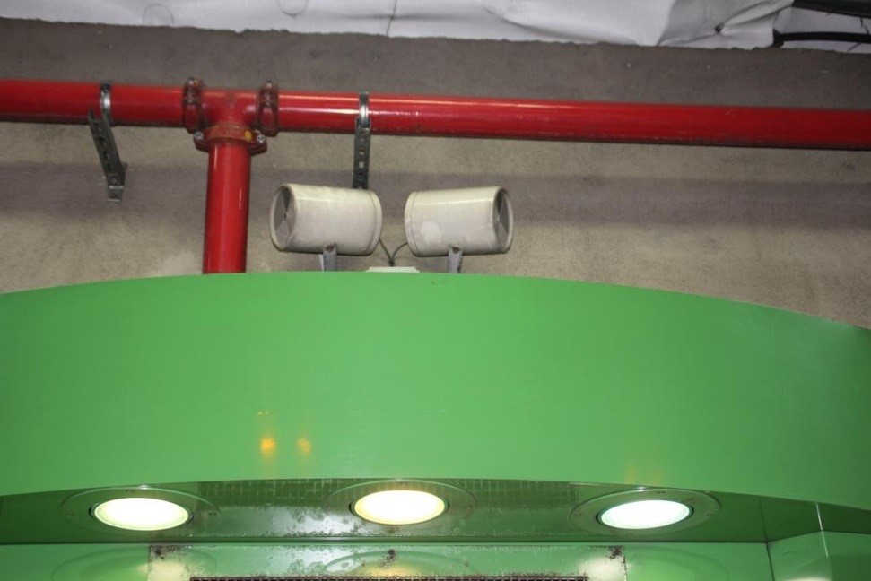
Figure 1: Sound beacons above an emergency exit
These sound beacons are located in the part of the tunnel open to traffic and have the following objectives:
It is important to be able to adjust the sound level of these beacons in order to prevent reverberation phenomena and inaudibility.
The information that is announced can be:
In cross-border tunnels, announcements may be made in the language of each country on which the tunnel is located.
A fire involving one or more vehicles is the most feared incident in a tunnel. Consequently, tunnels are equipped with numerous items of equipment to mitigate such hazards.

This equipment includes:
In addition to this equipment, there are often specific requirements in terms of:
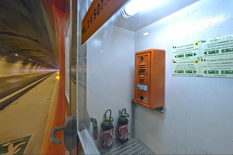
Figure1: Manual fire extinguishers in an emergency station
Among the means used to fight fires in road tunnel, smoke control systems are important economic and strategic considerations. The main purposes of smoke control systems are to:
A longitudinal ventilation system keeps the area upstream of the fire smoke-free, which means that, in theory, there is no need for escape routes. However, emergency exits may be required to account for the unexpected, such as the fire developing to a size that the ventilation system can no longer handle, or an explosion occurring.
Smoke extraction in transverse or semi-transverse ventilation systems are based upon the following three principles:
Smoke removal systems of this type will usually have a smoke extract duct, with openings or dampers for the capture of smoke, connected to extract fans. Additional information on the ventilation equipment and their specifications can be found in page Ventilation.
See pages Ventilation principles and Design and dimensioning for further information on the smoke control principles and design criteria.
The design of appropriate ventilation control scenarios for each possible fire situation is a very important part of the process: see Technical Report 2011 R02 "Road tunnels: Operational strategies for emergency ventilation". These scenarios can be simple, especially when the longitudinal strategy is applied, or involve a large number of measurement and ventilation devices in complex, transverse-ventilated tunnels (page Control and Monitoring provides additional information on this topic).
The interactions of the ventilation system design with other elements of a tunnel are numerous and diverse. In the case of transverse ventilation, for example, the required flow rates may impact the excavated section, with a potentially important impact on the construction cost. Ventilation also accounts for a large part of a tunnel's power supply requirements. It interacts closely with other safety equipment such as fire detection and fire fighting systems : see Chapter 5 "Fixed fire fighting systems in the context of tunnel safety systems" of the PIARC Report 2008 R07.
Finally, other parts of a tunnel than the main traffic space may require ventilation, most notably the emergency exits : see Section 5.3. "Escape route design" of PIARC report 2007 05.16 "Systems and equipment for fire and smoke control".
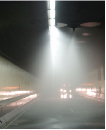
Fig. 1 : Fixed fire fighting system in operation
In a rapidly developing fire, smoke can quickly compromise the ability of users to self-rescue, while rapidly elevating temperatures can make the tunnel untenable and destroy safety systems. An FFFS has the potential to reduce the rates of fire growth and spread, thereby assisting the safety of motorists and the emergency services during the self-rescue and assisted-rescue phases of a fire. Other potential benefits of an FFFS are the protection of the tunnel assets from fire damage, and the avoidance or reduction of road network disruptions that may occur while a tunnel is being repaired following a fire incident.
Water-based deluge systems are by far the most common type of FFFS installed in tunnels at present. Both low-pressure and high-pressure systems are available, with the latter having smaller droplet sizes. Other water-based systems, including foam systems, have also been installed in tunnels. The selection of the appropriate FFFS should be based on cost-benefit analysis.
Except where the installation of an FFFS is prescribed by a country's tunnel design guidelines, the following steps are recommended to support the decision as to whether such a system should be installed:
FFFS must be considered in the context of other critical safety systems such as ventilation. Rapid and accurate incident detection and FFFS response are essential components to achieve the best possible FFFS performance.
Report 2016 R03 provides information about the types of systems available, their use in road tunnels in various countries and advice on the design and selection of appropriate FFFS. Where FFFS are adopted, it is essential that they are correctly designed, installed, integrated, commissioned, maintained, tested and operated.
The materials used in tunnel construction have to possess adequate resistance to fire to ensure integrity during evacuation and fire fighting.
Section VII.3 "Fire reaction of materials" of technical report 05.05.B "Fire and Smoke Control in Tunnels" discusses the fire properties of tunnel materials, indicating that the specifications set for materials should include requirements concerning their properties in the event of a fire. Desirable properties include:
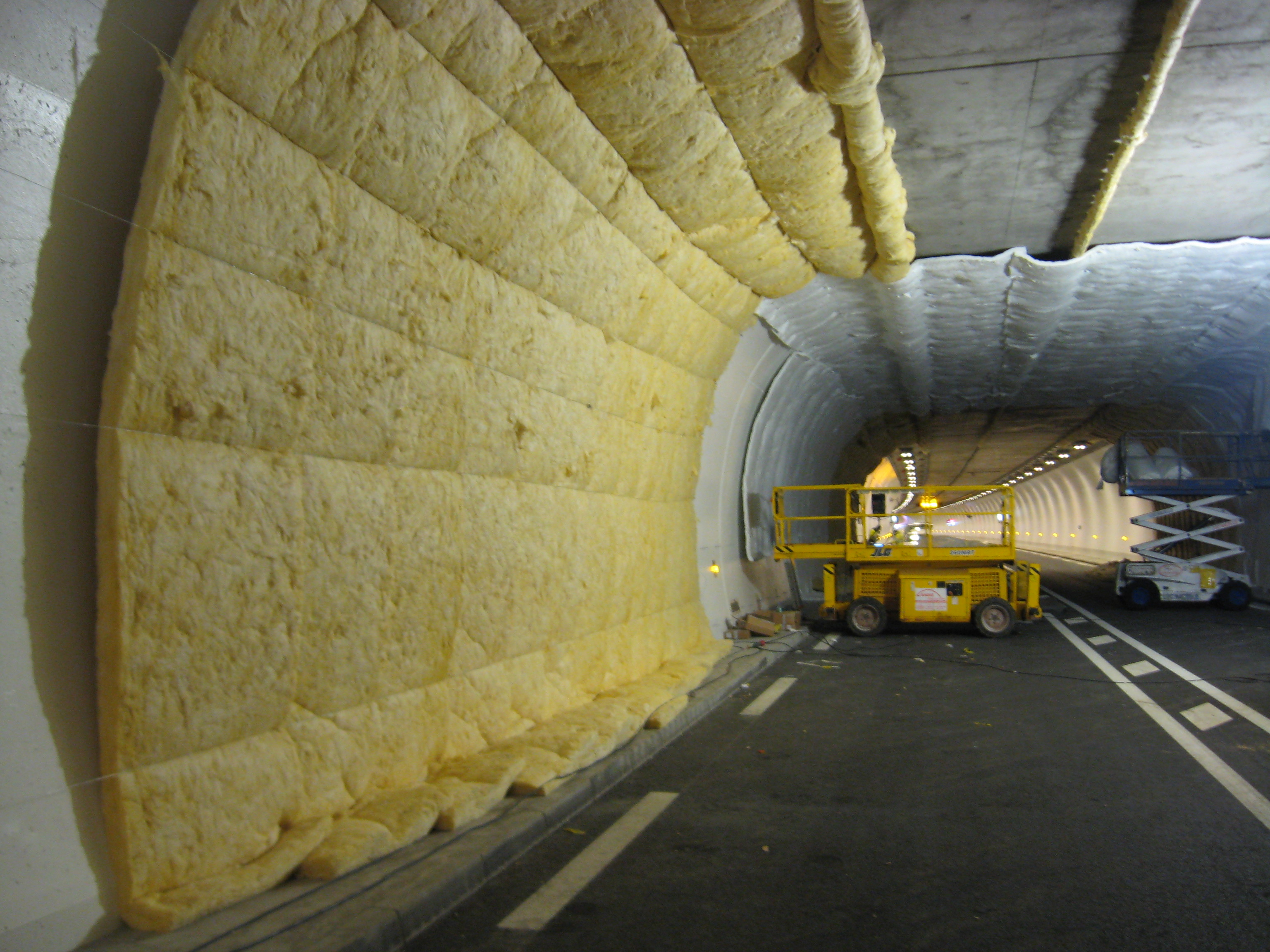
Figure 1: Setting up a test to verify the reaction to fire of tunnel wall cladding
The possibility that materials might produce chemically corrosive or toxic substances during combustion and that these might penetrate the surface of the concrete and cause subsequent corrosion should also be considered. This also applies to any coatings that might be used. In case of polypropylene fibres being specified to reduce the risk of spalling, the issue of concrete durability after any significant fire event should be considered. This is because there will be increased porosity within the concrete where fibres have melted, leading to increased vulnerability to carbonation or chloride attack.
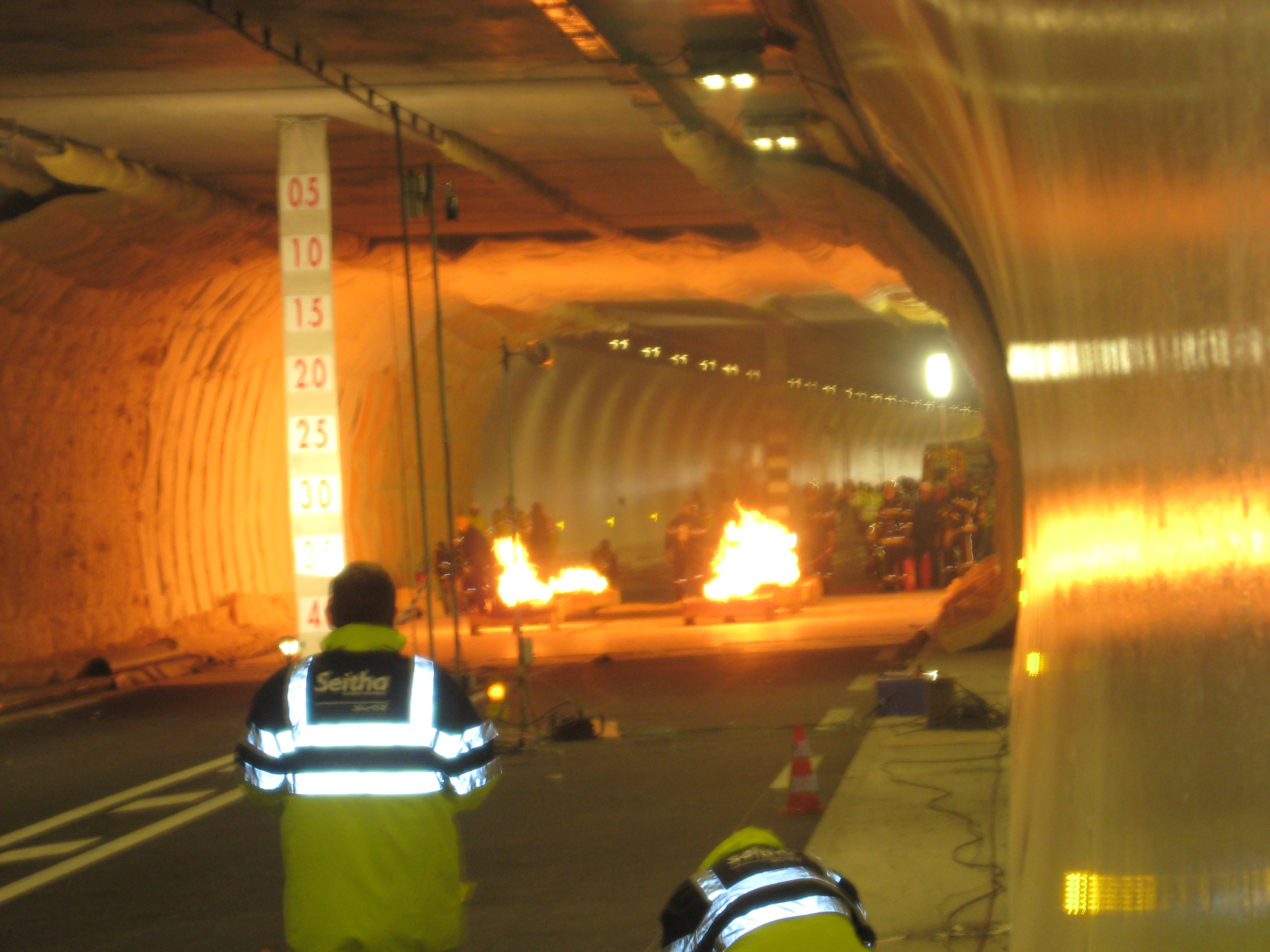
Figure 2: Test to verify the reaction to fire of tunnel wall cladding
The fire resistance of a structure can be characterised by the time which elapses between the start of a fire and the time when the structure does not ensure its function any longer, due to unacceptable deformation or collapse.
Chapter 7 "Design Criteria for Structure Resistance to Fire" of technical report 2007 05.16.B "Systems and Equipment for Fire and Smoke Control in Road Tunnels" summarises the objectives of structural fire resistance in tunnels as follows:
A supplementary objective is to limit the time during which traffic will be disrupted due to the repairs after a fire.
An overview of the subject was published in Chapter VII.4 "Fire resistance of structures" of technical report 1999 05.05.B "Fire and Smoke Control in Tunnels".
The fire resistance of structures is described in relation to different time-temperature curves. Figure 1 shows the ISO 834 curve, the Dutch RWS curve, German ZTV curve and a French 'increased' Hydrocarbon curve, HCinc, in which the temperatures are multiplied by a factor of 1300/1100 from the basic Hydrocarbon (HC) curve of Eurocode 1 Part 2-2.
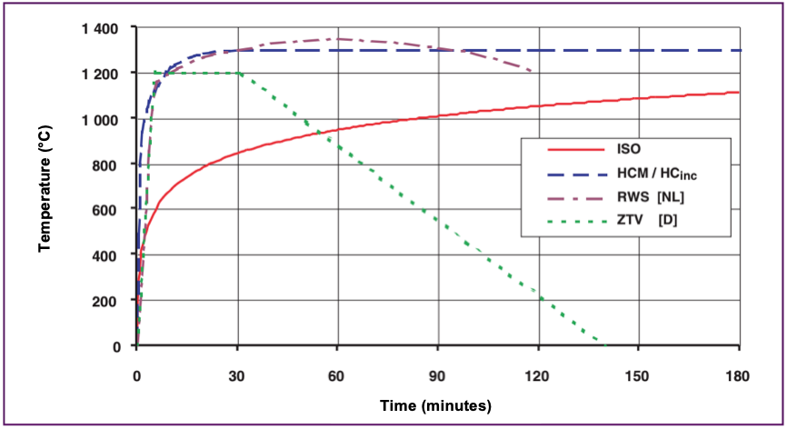
Figure 1: Temperature versus time curves for ISO, HCinc, ZTV and RWS standards (Routes/Roads No. 324)
Design criteria for resistance to fire in tunnels have been agreed between the World Road Association (PIARC) and the International Tunnelling Association, as presented in the Routes/Roads article "PIARC Design Criteria for Resistance to Fire for Road Tunnel Structures" (2004), and published as a PIARC recommendation in Chapter 7 "Design Criteria for Structure Resistance to Fire" of technical report 2007 05.16.B.
A summary of the proposals is presented in Table 1. On the basis of the time-temperature curves presented in figure 1 above, table 1 identifies the curve to be chosen and the duration during which this curve must be respected. This information is given for different types of main structures and secondary structures and for two types of traffic: cars/vans and lorries/tankers.
|
Traffic Type |
Main Structure |
Secondary Structures (4) |
||||||
|---|---|---|---|---|---|---|---|---|
| - | Immersed or Under/Inside Superstructure |
Tunnel in Unstable Ground | Tunnel in Stable Ground | Cut & Cover | Air Ducts (5) | Emergency Exits to Open Air |
Emergency Exits to Other Tube |
Shelters (6) |
| Cars Vans |
ISO 60 min |
ISO 60 min |
See note (2) | See note (2) | ISO 60 min |
ISO 30 min |
ISO 60 min |
ISO 60 min |
| Lorries Tankers |
RWS/HCinc 120 min (1) |
RWS/HCinc 120 min (1) |
See note (3) | See note (3) | ISO 120 min |
ISO 30 min |
RWS/HCinc 120 min |
RWS/HCinc 120 min (7) |
Notes
(1) 180 min may be required for very heavy traffic density of lorries carrying combustible goods.
(2) Safety is not a criterion and does not require any fire resistance (other than avoiding progressive collapse). Taking into account other objectives may lead to the following requirements:
(3) Safety is not a criterion and does not require any fire resistance (other than avoiding progressive collapse). Taking into account other objectives may lead to the following requirements:
(4) Other secondary structures: should be defined on a project-specific basis.
(5) In case of transverse ventilation.
(6) Shelters should be connected to the open air.
(7) A longer time may be considered if there is a very heavy volume of lorries carrying combustible goods and evacuation from the shelters is not possible within 120 min.
The consequences of failure will influence the requirements for fire resistance. This depends on the type of tunnel. In an immersed tunnel, for example, a local collapse can cause the whole tunnel to be flooded whereas local collapse in a cut-and-cover tunnel may have very limited consequences. A basic requirement is that progressive collapse must be prevented and vital longitudinal systems, such as an electrical supply or communication cables, are not cut off.
The materials used in tunnel structures involve different precautions for fire protection. Section VII.3 "Fire reaction of materials" of the report 1999 05.05.B "Fire and Smoke Control in Tunnels" discusses the characteristics of rock tunnel linings versus reinforced concrete. The intensity of the heat generated during a major fire may cause reinforced concrete to lose its supporting function. The role of insulation using fire-resistant protection can be applied to prevent early damage to the structure. The fire resistance of the total construction (type and depth of reinforcement/prestressing, additional protection, etc.) needs to be considered.
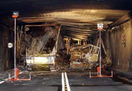
Figure 3: Damaged structure of the Gothard tunnel following the fire in 2001
Attention must be given to the fire resistance of the ventilation system so that its design performance is not impaired by failure. Therefore it is necessary to examine the consequences of a local collapse of a duct in case of fire.
Escape routes are only used during the first phase of the fire for the escape of trapped people. It must be possible to use such routes for a period of at least 30 minutes. In cases where these routes are also used by the rescue and fire teams, the period may be longer.
To avoid fire spreading into an adjacent tube or escape route, emergency doors, emergency recesses and other equipment located between two traffic tubes, should remain intact during a specified period of time. The whole emergency door and surrounding construction, including the door frame, should resist fire for at least a 30 minute fire exposure. For a door between two traffic tubes, a much longer resistance is required, for example 1 to 2 hours.
In terms of resistance to high temperatures, tunnel equipment and cables can be broadly grouped as either fire-rated or unprotected.
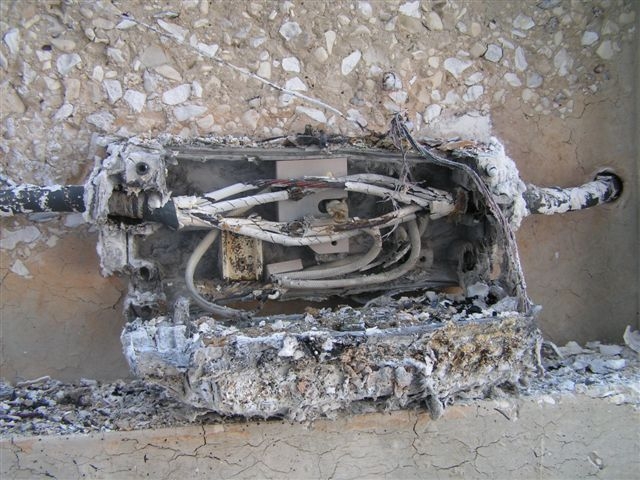
Figure 1: Damaged cables following a fire
Protected equipment and cables with variable levels of resistance to fire include, for example:
Unprotected items of equipment such as traffic signs, cameras and public address (PA) speakers have working temperatures typically up to 50°C, and are likely to fail at relatively low temperatures. Materials include:
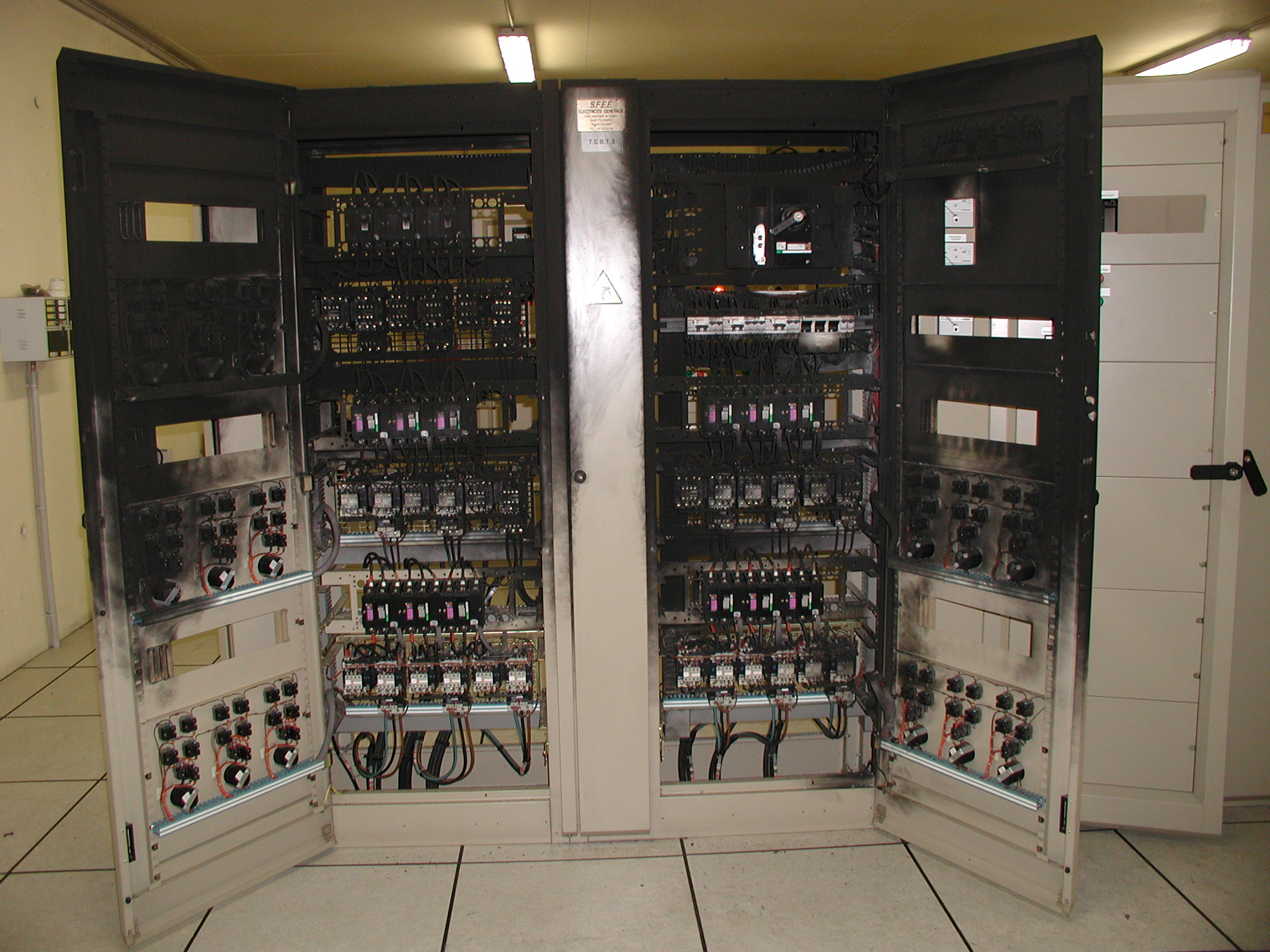
Figure 2: Damaged electrical enclosure following a fire
All fittings used for the fixing of equipment to the structures should be considered in terms of their behaviour in fires.
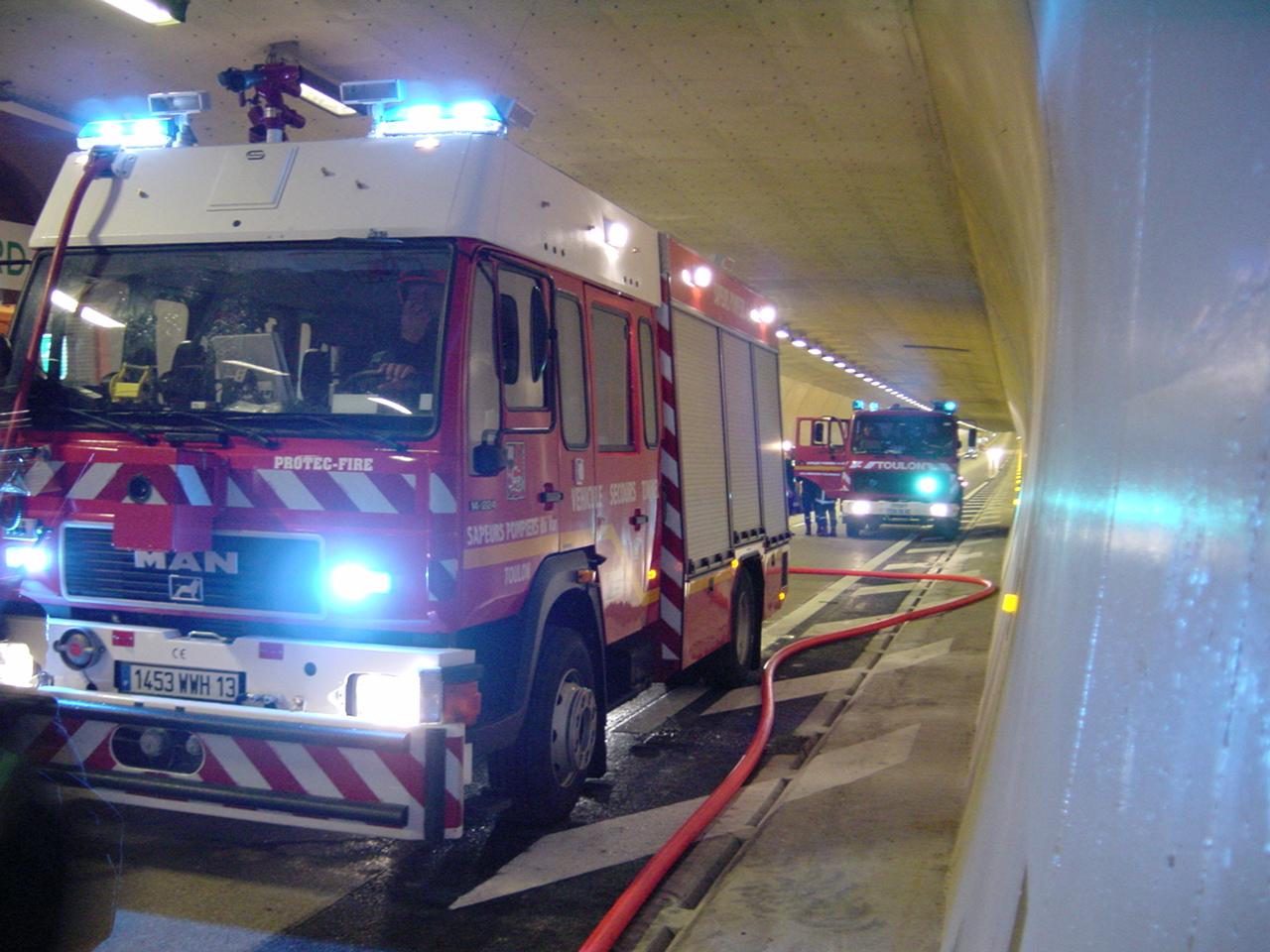
Figure1: Fire service intervention following a tunnel fire
This equipment includes:
A tunnel is an enclosed structure that usually does not permit the natural transmission of radio waves to travel very far into the tunnel. To ensure that the emergency services and maintenance personnel can remain in radio contact with their colleagues outside the tunnel, it is necessary to install equipment that will provide this service.
Multiple frequencies can be retransmitted into the tunnel by taking “off-air” radio signals and re-transmitting them into the tunnel to allow:
There are a very large number of services whose frequencies can be retransmitted into the tunnel. However, not all of them are retransmitted, due to cost and feasibility issues. As a general rule, most frequencies used by the rescue services, frequencies used by the operator, a few FM and or DAB frequencies and frequencies of cell phone operators are generally retransmitted.
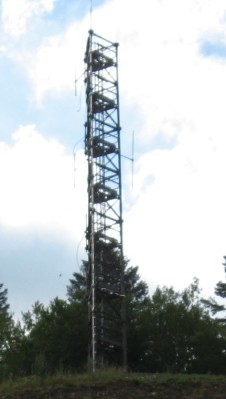
Fig 1: Outside antenna to receive radio stations “off-air”
There is usually no mandatory requirement to provide mobile telephone coverage inside tunnels. However, since the majority of tunnel users have mobile phones, it is believed to be a safer option to facilitate mobile coverage, encouraging stranded motorists to use their mobiles from inside their vehicles rather than getting out of their vehicles and using the roadside emergency telephones. Tunnel owners therefore often provide the mobile phone operators with facilities inside the technical rooms to allow them to install equipment that will provide continuing mobile phone coverage inside the tunnel.
See page on Radio break-in systems including Voice Break-In facilities, for further information.
The purpose of ventilation in a road tunnel is to provide adequate fresh air and in the event of a fire, to control smoke.
Fresh air is provided through entirely automated systems, based on information from various sensors located throughout the tunnel (opacimeters, CO sensors, NOx sensors…).
For smoke extraction, the nature of the tunnel and in particular its level of surveillance (presence or not of a manned control centre 24/7), will dictate how the ventilation is controlled:
Each panel can activate smoke extraction, or stop it if required. In certain cases (reversible longitudinal ventilation system), the panels can also control the direction in which the smoke is blown.
If a smoke control panel is located at each portal, it is important to define which panel has priority over the other (for example, when the first panel is activated, it over-rides the second), in order to avoid contradictory commands if fire officers are located at both portals.
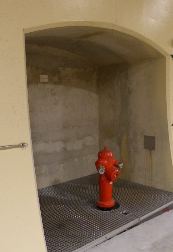
Fig 1: Fire hydrant
Hose valves are required within the road tunnel to provide a point of connection for the Fire Brigade to attach fire hoses and gain access to the water supply. Hydrants should be installed at regular intervals within the tunnel (see Section 6.3.3 "Water supply" of report 05.05.B 1999). The hydrant connections must be compatible with the responding local fire brigade(s).
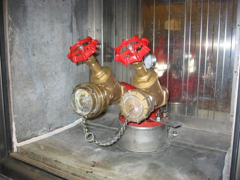
Fig 2. Fire hose valves