
A fire involving one or more vehicles is the most feared incident in a tunnel. Consequently, tunnels are equipped with numerous items of equipment to mitigate such hazards.
This equipment includes:
In addition to this equipment, there are often specific requirements in terms of:
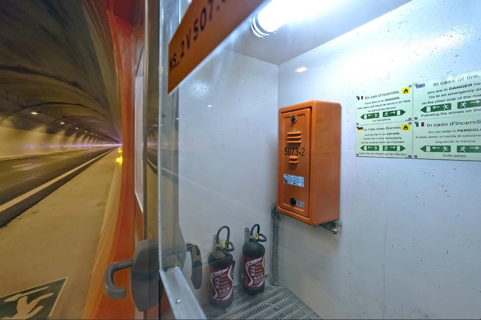
Figure1: Manual fire extinguishers in an emergency station
Among the means used to fight fires in road tunnel, smoke control systems are important economic and strategic considerations. The main purposes of smoke control systems are to:
A longitudinal ventilation system keeps the area upstream of the fire smoke-free, which means that, in theory, there is no need for escape routes. However, emergency exits may be required to account for the unexpected, such as the fire developing to a size that the ventilation system can no longer handle, or an explosion occurring.
Smoke extraction in transverse or semi-transverse ventilation systems are based upon the following three principles:
Smoke removal systems of this type will usually have a smoke extract duct, with openings or dampers for the capture of smoke, connected to extract fans. Additional information on the ventilation equipment and their specifications can be found in page Ventilation.
See pages Ventilation principles and Design and dimensioning for further information on the smoke control principles and design criteria.
The design of appropriate ventilation control scenarios for each possible fire situation is a very important part of the process: see Technical Report 2011 R02 "Road tunnels: Operational strategies for emergency ventilation". These scenarios can be simple, especially when the longitudinal strategy is applied, or involve a large number of measurement and ventilation devices in complex, transverse-ventilated tunnels (page Control and Monitoring provides additional information on this topic).
The interactions of the ventilation system design with other elements of a tunnel are numerous and diverse. In the case of transverse ventilation, for example, the required flow rates may impact the excavated section, with a potentially important impact on the construction cost. Ventilation also accounts for a large part of a tunnel's power supply requirements. It interacts closely with other safety equipment such as fire detection and fire fighting systems : see Chapter 5 "Fixed fire fighting systems in the context of tunnel safety systems" of the PIARC Report 2008 R07.
Finally, other parts of a tunnel than the main traffic space may require ventilation, most notably the emergency exits : see Section 5.3. "Escape route design" of PIARC report 2007 05.16 "Systems and equipment for fire and smoke control".
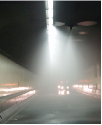
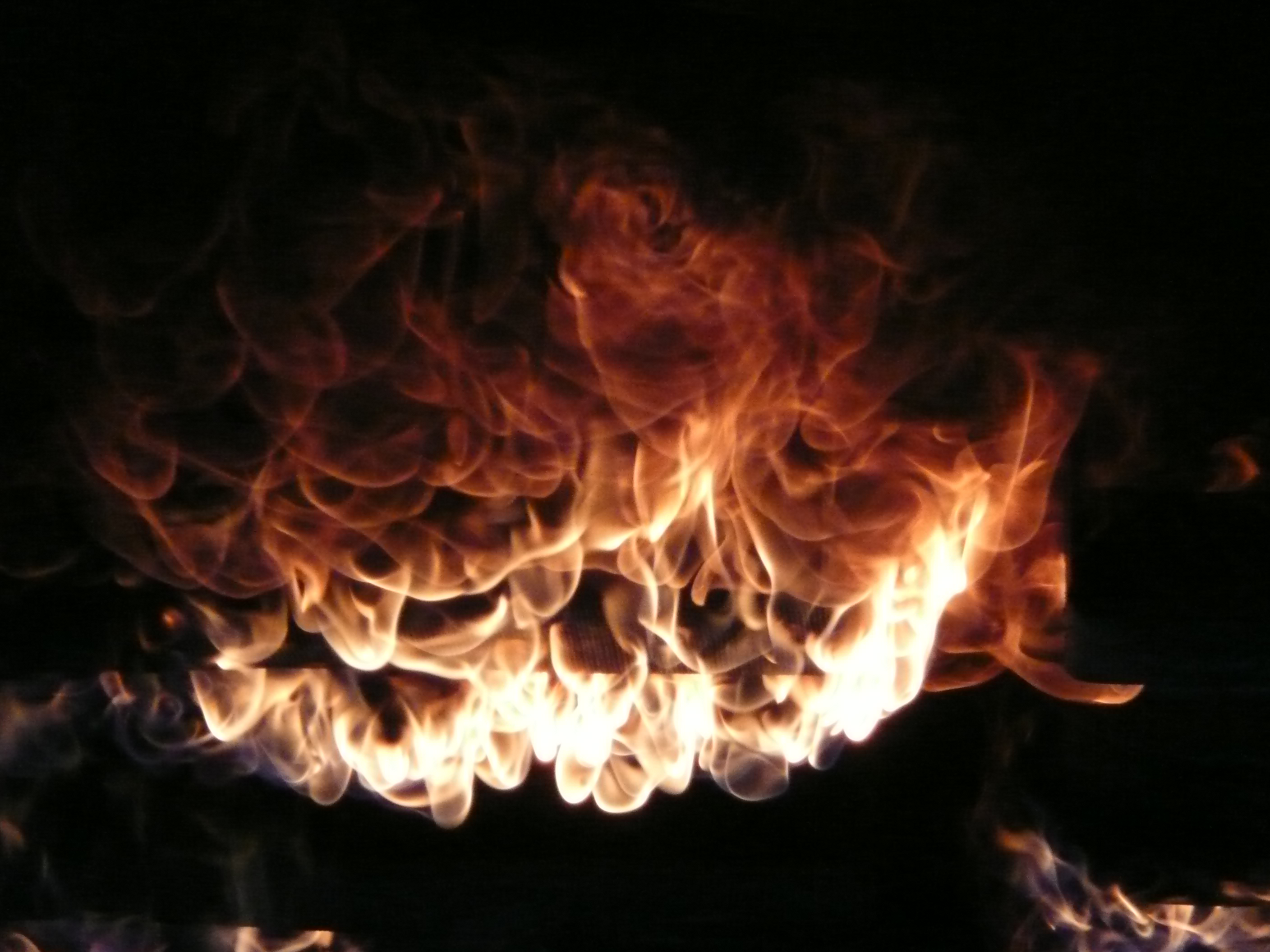
Fig. 1 : Fixed fire fighting system in operation
In a rapidly developing fire, smoke can quickly compromise the ability of users to self-rescue, while rapidly elevating temperatures can make the tunnel untenable and destroy safety systems. An FFFS has the potential to reduce the rates of fire growth and spread, thereby assisting the safety of motorists and the emergency services during the self-rescue and assisted-rescue phases of a fire. Other potential benefits of an FFFS are the protection of the tunnel assets from fire damage, and the avoidance or reduction of road network disruptions that may occur while a tunnel is being repaired following a fire incident.
Water-based deluge systems are by far the most common type of FFFS installed in tunnels at present. Both low-pressure and high-pressure systems are available, with the latter having smaller droplet sizes. Other water-based systems, including foam systems, have also been installed in tunnels. The selection of the appropriate FFFS should be based on cost-benefit analysis.
Except where the installation of an FFFS is prescribed by a country's tunnel design guidelines, the following steps are recommended to support the decision as to whether such a system should be installed:
FFFS must be considered in the context of other critical safety systems such as ventilation. Rapid and accurate incident detection and FFFS response are essential components to achieve the best possible FFFS performance.
Report 2016 R03 provides information about the types of systems available, their use in road tunnels in various countries and advice on the design and selection of appropriate FFFS. Where FFFS are adopted, it is essential that they are correctly designed, installed, integrated, commissioned, maintained, tested and operated.
The materials used in tunnel construction have to possess adequate resistance to fire to ensure integrity during evacuation and fire fighting.
Section VII.3 "Fire reaction of materials" of technical report 05.05.B "Fire and Smoke Control in Tunnels" discusses the fire properties of tunnel materials, indicating that the specifications set for materials should include requirements concerning their properties in the event of a fire. Desirable properties include:
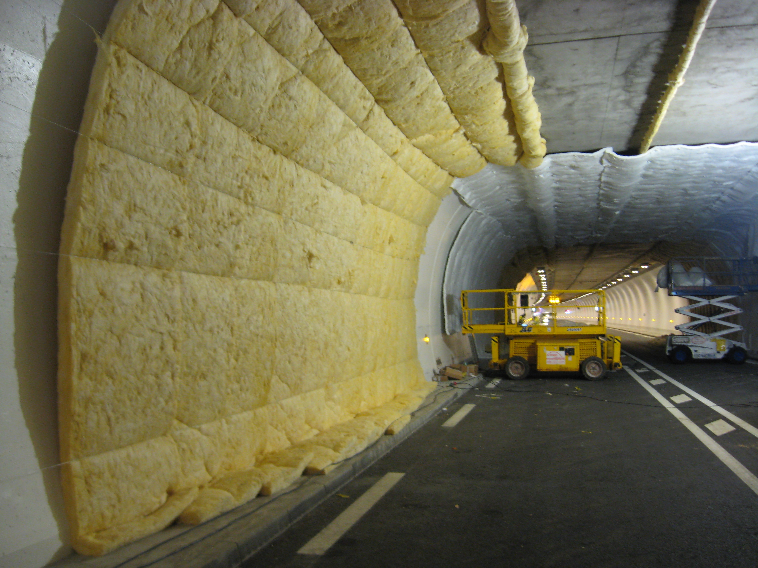
Figure 1: Setting up a test to verify the reaction to fire of tunnel wall cladding
The possibility that materials might produce chemically corrosive or toxic substances during combustion and that these might penetrate the surface of the concrete and cause subsequent corrosion should also be considered. This also applies to any coatings that might be used. In case of polypropylene fibres being specified to reduce the risk of spalling, the issue of concrete durability after any significant fire event should be considered. This is because there will be increased porosity within the concrete where fibres have melted, leading to increased vulnerability to carbonation or chloride attack.
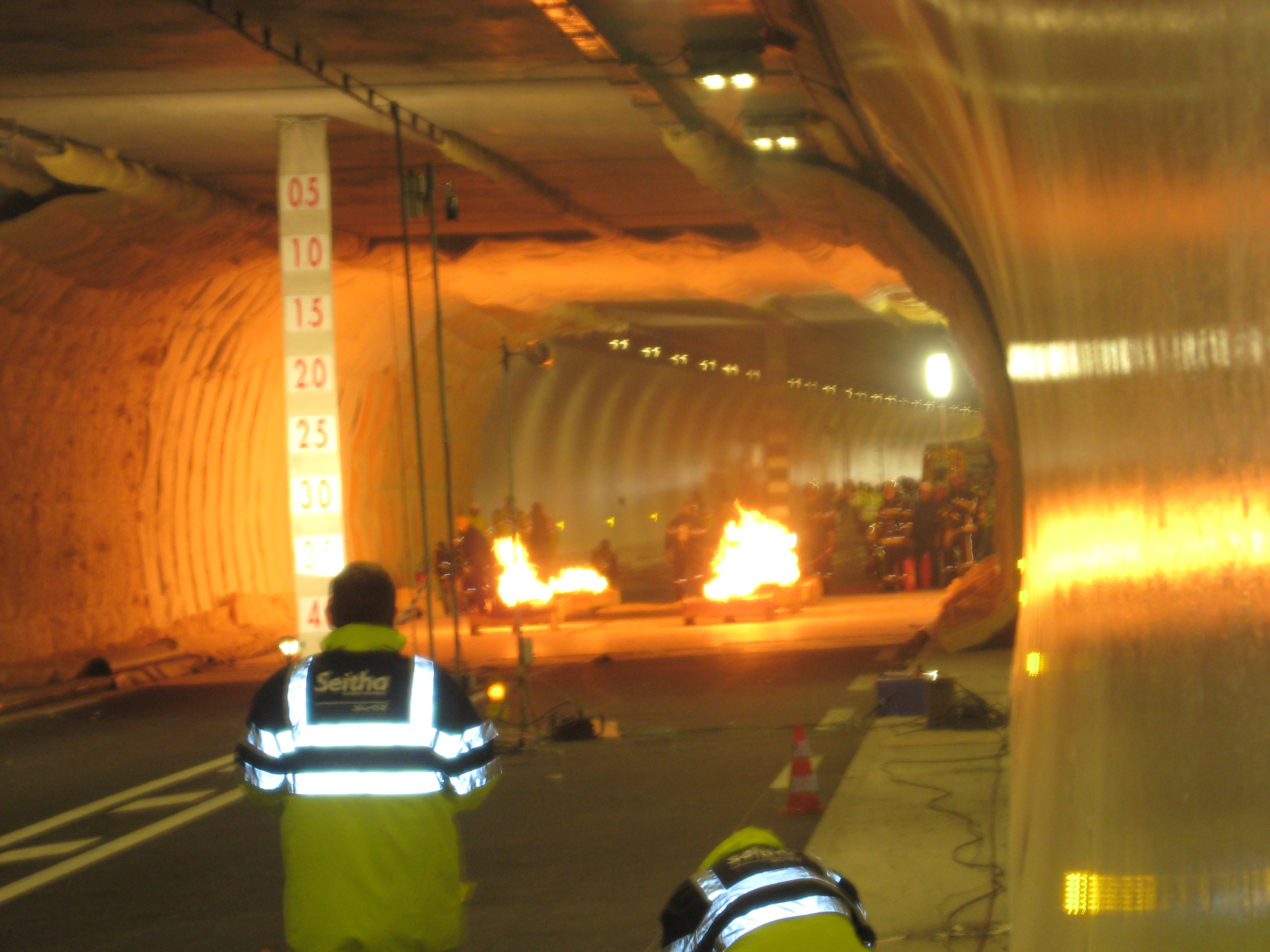
Figure 2: Test to verify the reaction to fire of tunnel wall cladding
The fire resistance of a structure can be characterised by the time which elapses between the start of a fire and the time when the structure does not ensure its function any longer, due to unacceptable deformation or collapse.
Chapter 7 "Design Criteria for Structure Resistance to Fire" of technical report 2007 05.16.B "Systems and Equipment for Fire and Smoke Control in Road Tunnels" summarises the objectives of structural fire resistance in tunnels as follows:
A supplementary objective is to limit the time during which traffic will be disrupted due to the repairs after a fire.
An overview of the subject was published in Chapter VII.4 "Fire resistance of structures" of technical report 1999 05.05.B "Fire and Smoke Control in Tunnels".
The fire resistance of structures is described in relation to different time-temperature curves. Figure 1 shows the ISO 834 curve, the Dutch RWS curve, German ZTV curve and a French 'increased' Hydrocarbon curve, HCinc, in which the temperatures are multiplied by a factor of 1300/1100 from the basic Hydrocarbon (HC) curve of Eurocode 1 Part 2-2.
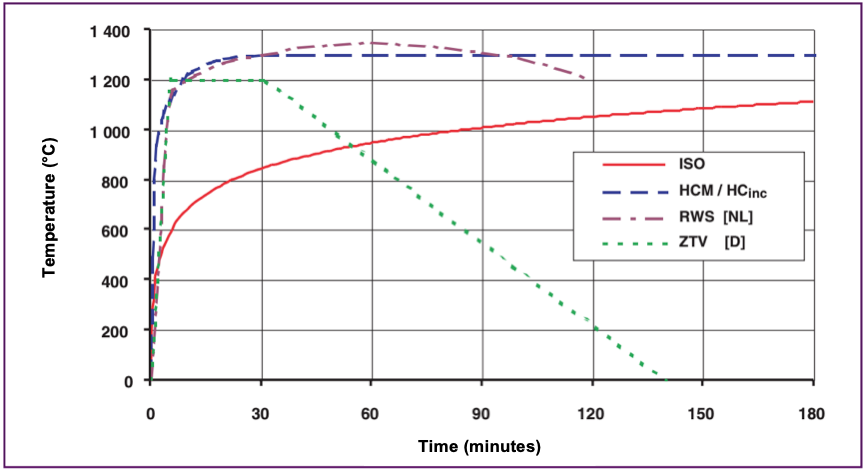
Figure 1: Temperature versus time curves for ISO, HCinc, ZTV and RWS standards (Routes/Roads No. 324)
Design criteria for resistance to fire in tunnels have been agreed between the World Road Association (PIARC) and the International Tunnelling Association, as presented in the Routes/Roads article "PIARC Design Criteria for Resistance to Fire for Road Tunnel Structures" (2004), and published as a PIARC recommendation in Chapter 7 "Design Criteria for Structure Resistance to Fire" of technical report 2007 05.16.B.
A summary of the proposals is presented in Table 1. On the basis of the time-temperature curves presented in figure 1 above, table 1 identifies the curve to be chosen and the duration during which this curve must be respected. This information is given for different types of main structures and secondary structures and for two types of traffic: cars/vans and lorries/tankers.
|
Traffic Type |
Main Structure |
Secondary Structures (4) |
||||||
|---|---|---|---|---|---|---|---|---|
| - | Immersed or Under/Inside Superstructure |
Tunnel in Unstable Ground | Tunnel in Stable Ground | Cut & Cover | Air Ducts (5) | Emergency Exits to Open Air |
Emergency Exits to Other Tube |
Shelters (6) |
| Cars Vans |
ISO 60 min |
ISO 60 min |
See note (2) | See note (2) | ISO 60 min |
ISO 30 min |
ISO 60 min |
ISO 60 min |
| Lorries Tankers |
RWS/HCinc 120 min (1) |
RWS/HCinc 120 min (1) |
See note (3) | See note (3) | ISO 120 min |
ISO 30 min |
RWS/HCinc 120 min |
RWS/HCinc 120 min (7) |
Notes
(1) 180 min may be required for very heavy traffic density of lorries carrying combustible goods.
(2) Safety is not a criterion and does not require any fire resistance (other than avoiding progressive collapse). Taking into account other objectives may lead to the following requirements:
(3) Safety is not a criterion and does not require any fire resistance (other than avoiding progressive collapse). Taking into account other objectives may lead to the following requirements:
(4) Other secondary structures: should be defined on a project-specific basis.
(5) In case of transverse ventilation.
(6) Shelters should be connected to the open air.
(7) A longer time may be considered if there is a very heavy volume of lorries carrying combustible goods and evacuation from the shelters is not possible within 120 min.
The consequences of failure will influence the requirements for fire resistance. This depends on the type of tunnel. In an immersed tunnel, for example, a local collapse can cause the whole tunnel to be flooded whereas local collapse in a cut-and-cover tunnel may have very limited consequences. A basic requirement is that progressive collapse must be prevented and vital longitudinal systems, such as an electrical supply or communication cables, are not cut off.
The materials used in tunnel structures involve different precautions for fire protection. Section VII.3 "Fire reaction of materials" of the report 1999 05.05.B "Fire and Smoke Control in Tunnels" discusses the characteristics of rock tunnel linings versus reinforced concrete. The intensity of the heat generated during a major fire may cause reinforced concrete to lose its supporting function. The role of insulation using fire-resistant protection can be applied to prevent early damage to the structure. The fire resistance of the total construction (type and depth of reinforcement/prestressing, additional protection, etc.) needs to be considered.
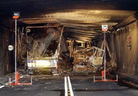
Figure 3: Damaged structure of the Gothard tunnel following the fire in 2001
Attention must be given to the fire resistance of the ventilation system so that its design performance is not impaired by failure. Therefore it is necessary to examine the consequences of a local collapse of a duct in case of fire.
Escape routes are only used during the first phase of the fire for the escape of trapped people. It must be possible to use such routes for a period of at least 30 minutes. In cases where these routes are also used by the rescue and fire teams, the period may be longer.
To avoid fire spreading into an adjacent tube or escape route, emergency doors, emergency recesses and other equipment located between two traffic tubes, should remain intact during a specified period of time. The whole emergency door and surrounding construction, including the door frame, should resist fire for at least a 30 minute fire exposure. For a door between two traffic tubes, a much longer resistance is required, for example 1 to 2 hours.
In terms of resistance to high temperatures, tunnel equipment and cables can be broadly grouped as either fire-rated or unprotected.
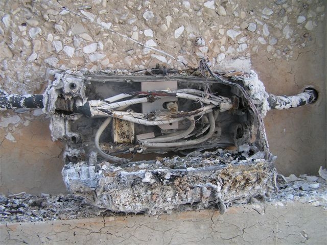
Figure 1: Damaged cables following a fire
Protected equipment and cables with variable levels of resistance to fire include, for example:
Unprotected items of equipment such as traffic signs, cameras and public address (PA) speakers have working temperatures typically up to 50°C, and are likely to fail at relatively low temperatures. Materials include:
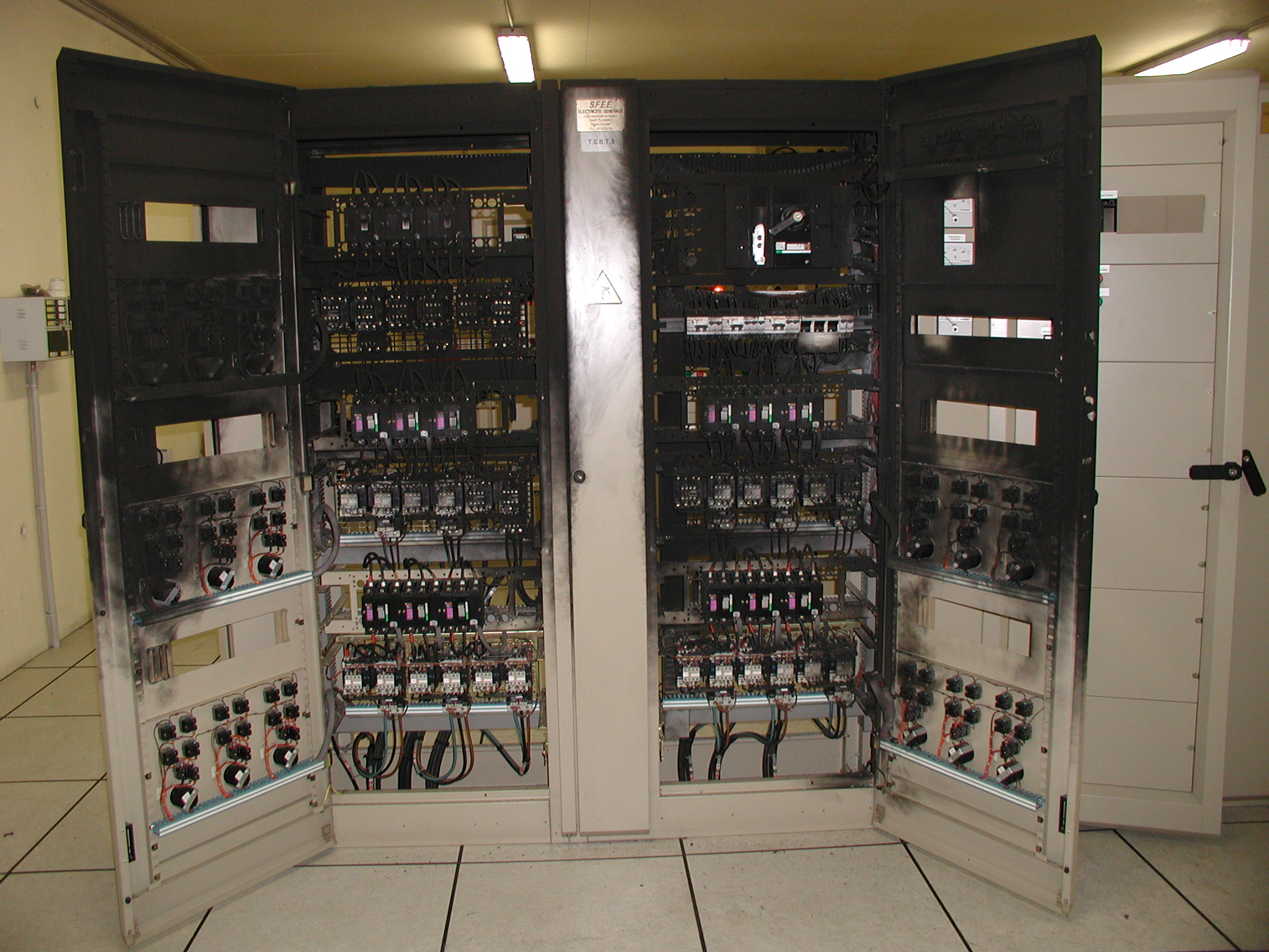
Figure 2: Damaged electrical enclosure following a fire
All fittings used for the fixing of equipment to the structures should be considered in terms of their behaviour in fires.