
This group comprises cross-functional equipment:
A significant amount of electric power is required to enable the equipment installed in the tunnel to operate. The electrical power supply systems (see page on Electrical power supply) must provide enough power for normal and emergency conditions. This also means that the system must work even in the case of blackouts, enabling vital equipment to keep functioning.
To guarantee user comfort and reduce the risks of accidents it is important to ensure adequate visibility and reduced concentration of contaminants. For these purposes, an adequate lighting system (see page on Tunnel lighting system) and ventilation system (see page on Tunnel ventilation system) are necessary. Ventilation is also crucial in emergency conditions, as it affects both fire development and smoke propagation. Depending on the traffic and the tunnel length, ventilation can be only natural, only mechanical or mixed natural/mechanical (e.g. natural in ordinary conditions and mechanical in emergency conditions).
The status of this equipment should also be monitored. For this reason, a SCADA system (see page on Supervisory Control And Data Acquisition systems (SCADA)) may be implemented.
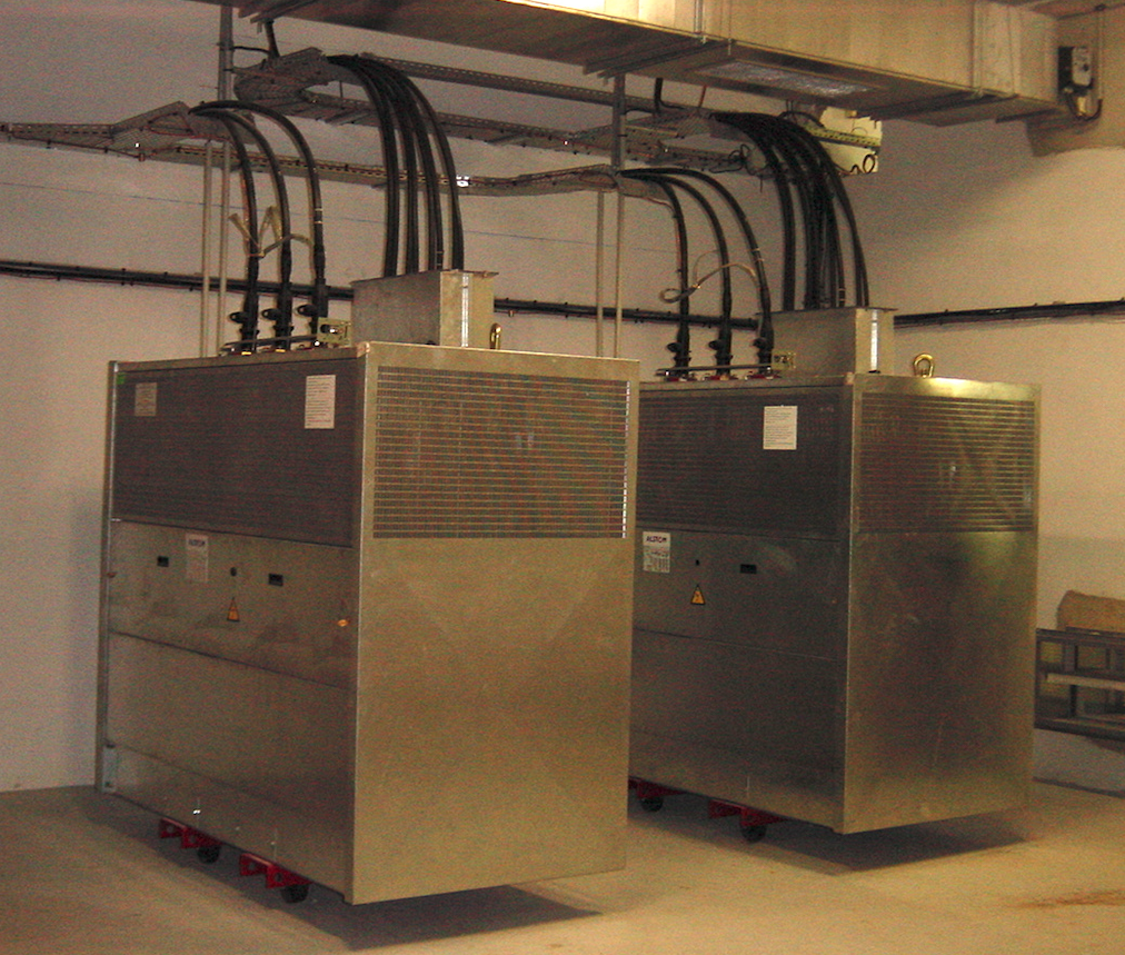
Figure 1: High voltage transformer
The power required for supplying a tunnel is directly related to the nature and number of equipment installed in it. Depending on the amount of electrical energy required (kWh), power may be supplied in low voltage or high voltage (Fig. 1).
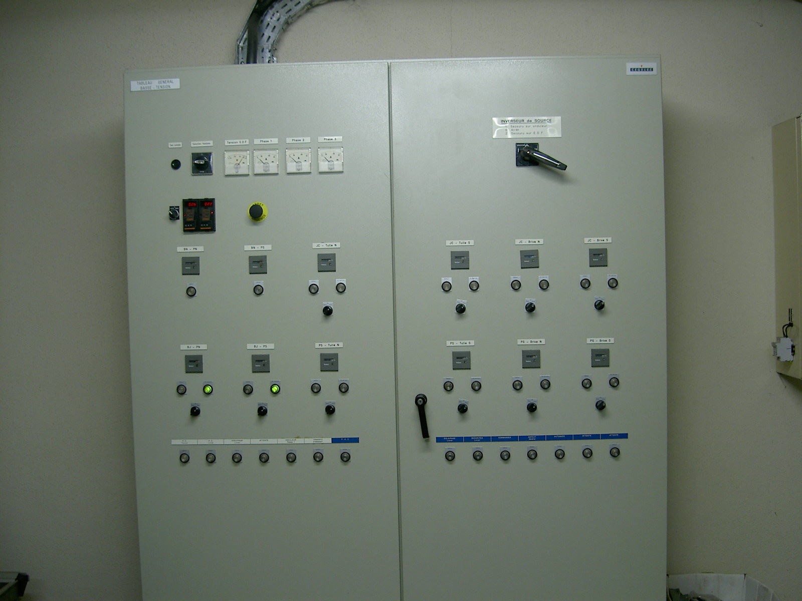
Figure 2: Example of an electrical enclosure
In the majority of tunnels, the natural penetration of light does not allow satisfactory visibility for users. It is therefore necessary to install artificial lighting to improve visibility conditions and comfort.
In terms of functionalities, the lighting installation must allow for:
Normal artificial lighting usually includes two successive zones:
In some tunnels, where there is a risk of glare at the exit, there is an exit reinforcement zone.
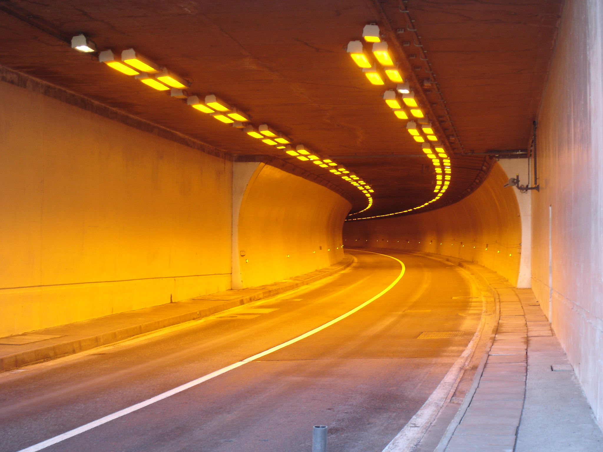
Figure 1: Example of reinforcement lighting in the Puymorens tunnel (France)
Entrance lighting
Motorists approaching a tunnel entrance will often experience what is known as the “black hole effect”. This is because luminance levels inside the tunnel are much lower than those outside and our eyes have difficulty adapting to the sudden difference. To alleviate this effect, a higher, “reinforced” level of lighting must therefore be provided at the tunnel entrance. This will ensure that drivers can see objects within the correct stopping distance before entering the tunnel. It will also help to prevent them from slowing down, which is important to maintain optimal traffic flow.
The amount of light required to avoid the black hole effect will depend on the bness outside the tunnel (sunny or cloudy weather). Luminance measurements at portals are normally used to determine and adjust the lighting levels required for the entrance zone.
In order to enable drivers’ eyes to adapt from the entrance zone lighting to the interior zone lighting, the entrance lighting level is gradually reduced as drivers move along the tunnel.
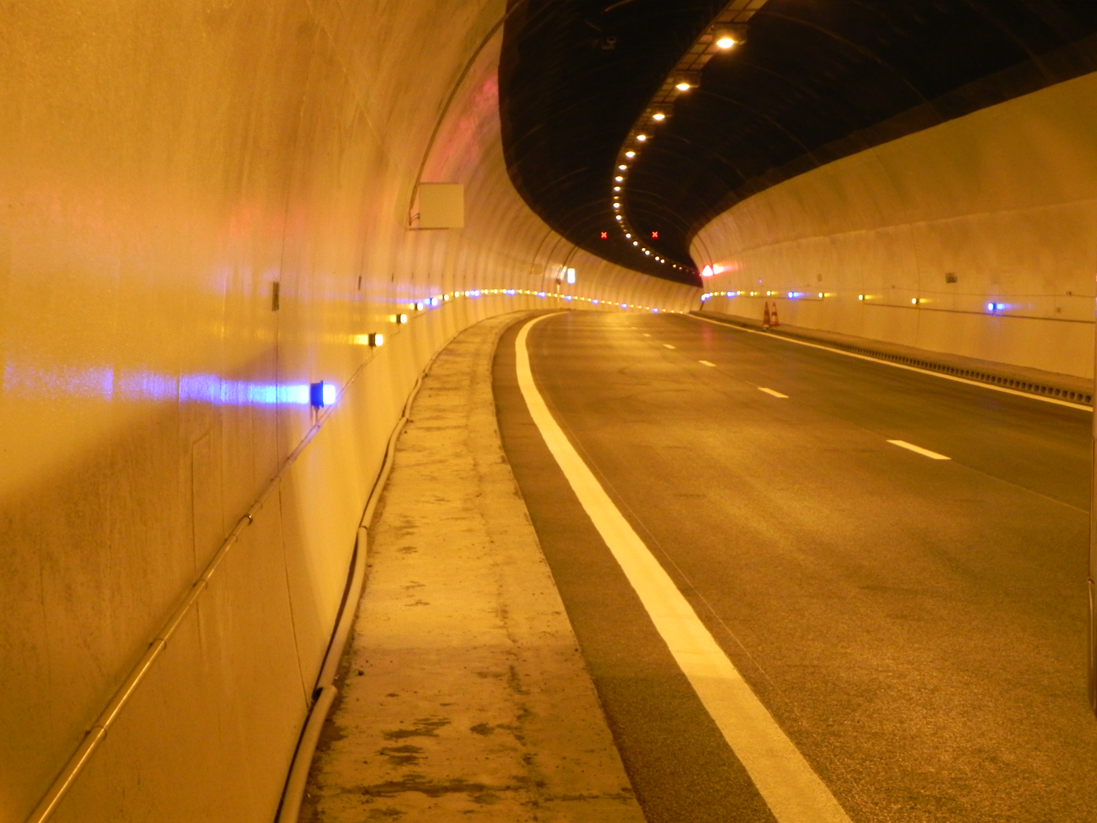
Figure 2: Example of interior zone lighting: Ponsérand tunnel (France)
Interior zone lighting
Once drivers have adapted to the lower luminance levels in the tunnel, sufficient lighting is needed in the interior zone for safe passage. Luminaires in the interior zone are therefore spaced at regular intervals, throughout the rest of the tunnel. Daytime and night-time levels of interior zone lighting are controlled by a photoelectric cell.
The design of a lighting installation should respect several criteria, notably those relating to the:
Several types of installations are possible; the most common are symmetrical lighting and counter-beam lighting.
Symetrical lighting
In symmetrical lighting systems, light is distributed symmetrically with respect to a plane perpendicular to the axis of the tunnel. An equal amount of light is sent towards each end of the tunnel. This system is generally used in the interior zone. It may be used in the entrance zone for tunnels which have a slow approach speed or where there is not enough room to install lighting fixtures above the carriageway.
Counterbeam lighting
Counterbeam systems project light in the direction of motorists, in conditions that avoid dazzling. This type of system, which should be fitted above the carriageway and facing the traffic flow, uses the photometric properties of the pavement (bness and specularity). It is suitable for use in entrance zones if there is sufficient room to install light fixtures above the carriageway. It has advantages in terms of investment costs and operation costs, especially when the approach speed is relatively high (>70 km/h).
In addition to the type of lighting system, attention should also be paid to coatings on the side walls of tunnels which can affect the overall efficiency of the chosen system. For symmetrical lighting, wall coatings should preferable be light coloured. In the case of counterbeam systems, darker, but more specular coatings are preferred.
Depending on the characteristics of the tunnel and the type of lighting system, the light fittings may be installed in one or more rows, above the road or at the top of the side walls.
The term « ventilation » combines several functions: pollution ventilation, smoke extraction, and sometimes ventilation for environmental protection purposes.
As explained on the page "Ventilation principles", in certain cases, ventilation in road tunnels can be achieved without the need of mechanical equipment (natural ventilation). However, in most of the tunnels with a length above some hundred meters, mechanical ventilation is unavoidable, which requires the design of a tunnel ventilation system (see the page on "Design and dimensioning").
The characteristics of the ventilation equipment to be installed strongly depend on the type of ventilation system for normal operation and fire scenarios.
Longitudinal ventilation systems utilize the tunnel tube as the “duct”. With the help of an air-jet placed in the tunnel air column, the flow resistance can be overcome by converting the jet momentum into static pressure.
The air jets can be placed at the tunnel entrance (Saccardo), blowing outside air into the tunnel or as ducted fans (usually called jetfans) along the tunnel, each one accelerating part of the tunnel air flow. Jetfans can work in both tunnel directions. (see section IV.2 “Longitudinal ventilation” of the PIARC report 1996 05.02 “Road Tunnels: Emissions, Environment, Ventilation”).
When a fan is installed into a tunnel a considerable decrease in the thrust occurs when the unit is close to the soffit or wall of the tunnel or in a niche. In those cases, it is recommended to use additional devices in order to maximize the installation factor. Examples are deflectors, inclined metal sheets, inclined silencers or nozzles. Section 4.4.4 "Ventilation" of the PIARC report 2017 R02 "Road Tunnel Operations: first steps towards a sustainable approach" provides some examples of efficiency improvement in longitudinal ventilation.
In some countries, air filtration systems have been put in place to mitigate the impact of vehicle emissions on ambient. Section 4.4.5 "Air cleaning" of the PIARC report 2017 R02 "Road Tunnel Operations: first steps towards a sustainable approach" provides some examples and approaches in different countries.
Jetfans operating in a tunnel can generate high noise levels, and can have adverse effects on speech transmission between people in the tunnel. This may become a safety issue when the noise level prevents the tunnel users from understanding what they are asked to do or when it makes it difficult for the firemen to communicate with each other. Therefore, some care must be taken in the assessment of sound emission by the jetfans.
Transverse ventilation uses ducts that run parallel to the tunnel. Two kinds of ducts are typically utilised:
Extraction for smoke control is usually concentrated to a zone smaller than the length of the duct by the addition of motorized, remotely controlled dampers, also known as “point extraction”. The fans serving the ducts are often located in ventilation plants close to the tunnel portals or shafts; however, many variations can exist.
The extraction fans must be sized to ensure the required extraction airflow rates for all fire locations in the tunnel. In the past, extract ducts were typically connected to the tunnel with a number of small, evenly spaced open vents. This concept has since evolved by replacing the small, open vents with larger vents equipped with remotely controlled motorised dampers and spaced further apart. The use of thermal fuses and panels has been assessed and found to have adverse effects: the effectiveness of the smoke control system using such thermal devices was found to be compromised by the untimely opening of some dampers and/or the opening of dampers in non-optimal locations.
The thermal resistance of the fans must ensure that the extraction of the hot smoke is possible with any configuration. Cables, junction boxes and all other non-protected parts of the ventilation system should have the same fire resistance as fans. For more details on fire resistance of other equipment, see section VII.5 "Fire resistance of equipment" of the 1999 PIARC report 05.05.B "Fire and Smoke Control in Road Tunnels". Additional information on maximum temperatures measured during the Memorial Tunnel and the Zwenberg Tunnel fire tests can also be found in this PIARC report 1999 05.05.
To fulfil their function, dampers must be able to withstand normal tunnel environmental conditions and to operate under emergency conditions.
Ventilation equipment should meet a number of specifications, including resistance to fire and acoustic performance. Chapter 4 "Ventilation" of Report 2006 05.16 and its appendices 12.3 "Jet Fan calculation procedure", 12.4. "Smoke dampers" and 12.6. "Sound impact of jet-fans" provide additional information on ventilation equipment for longitudinal and transverse systems.
Life cycle aspects need also to be accounted for in the design and selection of tunnel ventilation equipment. Additional information can be found in the PIARC report 2012 R14 "Life Cycle aspects of electrical road tunnel equipment".
In some cases, as for complex or urban tunnels, specific considerations need to be considered in the equipment requirements, as described in chapter 7 "Other equipment & operating facilities" of the PIARC report 2016 R19 "Road Tunnels: complex underground road networks".
Ventilation tests
Because the ventilation system plays a major role in tunnel safety, it is essential that it operates properly and effectively at all times. To achieve this goal, sets of tests have to be defined and adapted to specific tunnel specifications The primary objective of road tunnel ventilation system testing is twofold:
Three kinds of tests are usually performed in order to check the equipment and the safety objectives of the ventilation system:
It is generally impossible to perform integration tests with fires as large as the design fires. Most commonly, the main purpose of these tests is to train tunnel operators and members of the fire brigade.
The list of tests and corresponding timetables must be adapted to each particular tunnel, and depends on the installed equipment, traffic volume and degree of utilisation of the installations, and cover several aspects, including:
Chapter 8 "Operational responsibilities for emergencies" of the PIARC report 2007 05.16 "Systems and equipment for fire and smoke control" describes in more detail the appropriate ventilation tests for ventilation systems.
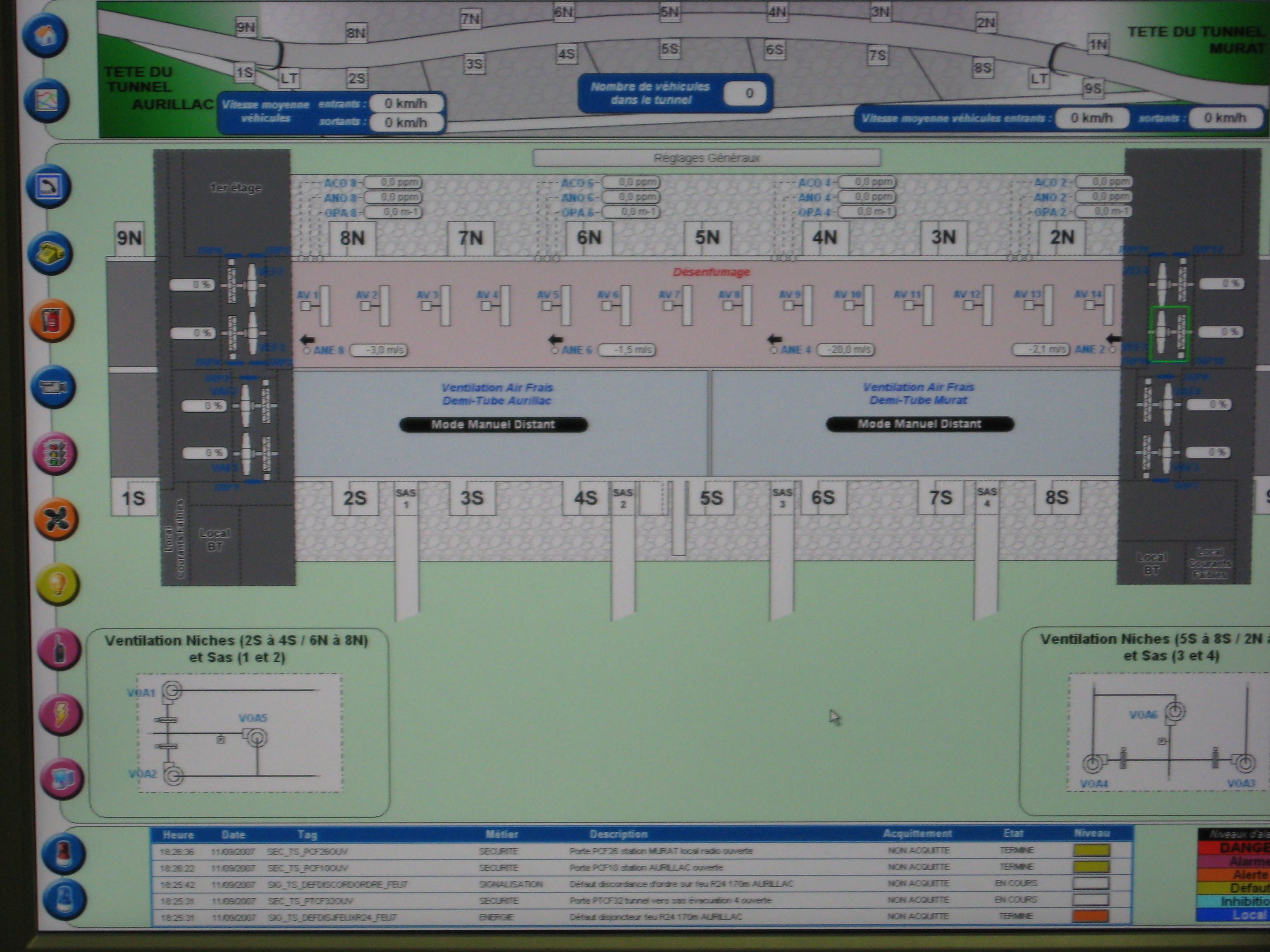
Figure 1: SCADA system operating ventilation in the Lioran tunnel (France)
Many devices are servo-controlled by sensors and operate automatically (e.g.lighting, ventilation.) according to pre-determined thresholds. Others are activated or deactivated depending on the operating conditions. It is thus useful for the operator to be able to remotely control them (such as signals, variable message signs, barriers, ventilation as fig. 1, lighting, pumps ...).
As the equipment may be operated very differently (continuously, occasionally, or very rarely), it is necessary for the operator to have information on the operational duration (hour used) of each item.
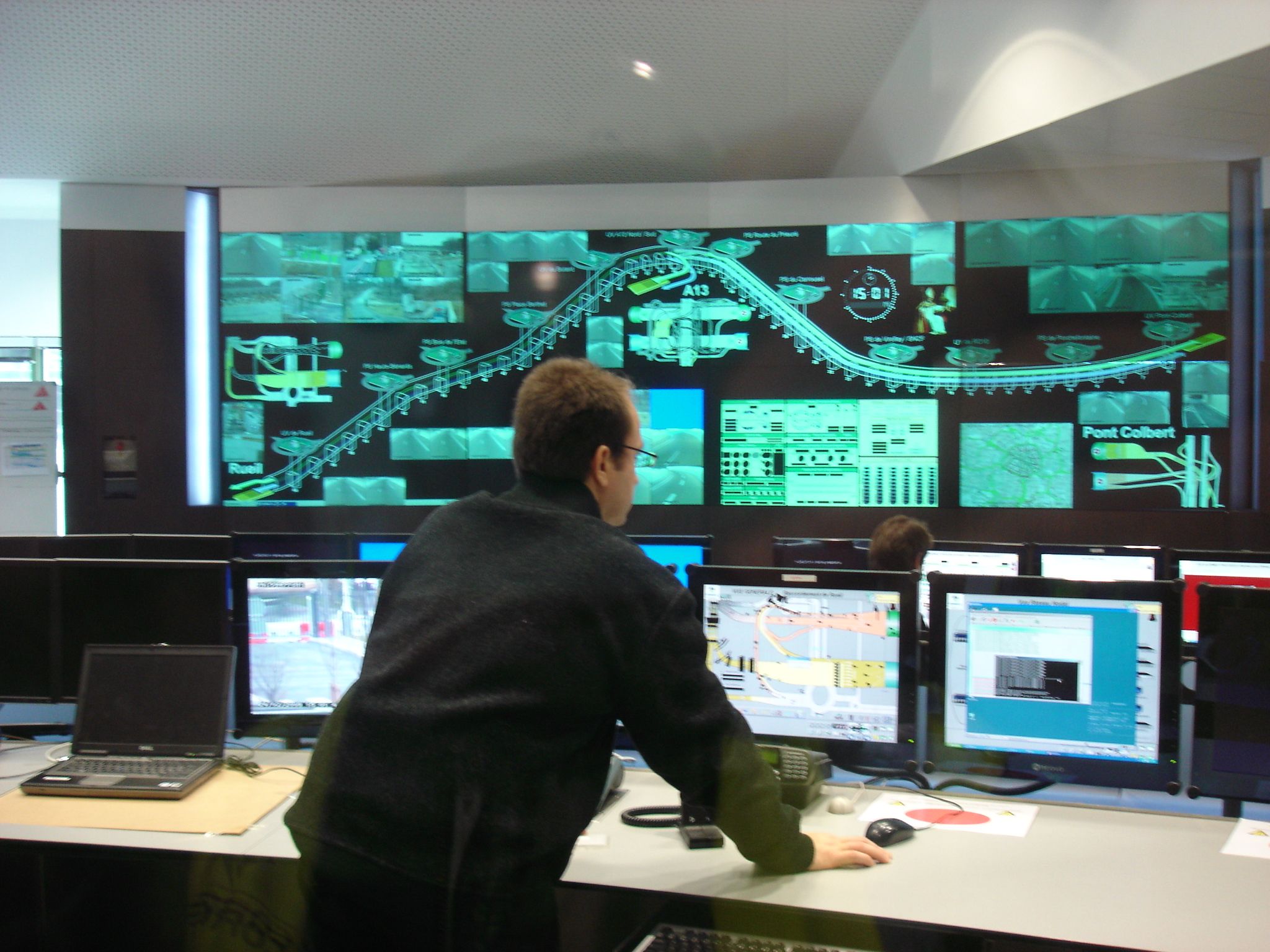
Figure 2: SCADA system in a tunnel control room
Several SCADA systems are available worldwide and their performance is being improved constantly. The systems installed in road tunnels of comparable characteristics are therefore rarely completely identical, even for the tunnels belonging to the same operator. Even so, the architectures follow certain rules that are widely prevalent:
With the development of internet and connected devices, SCADA are becoming increasingly vulnerable to cyber attacks. As they are the core of the safety process, efforts must be made to protecting them from this new threat.