
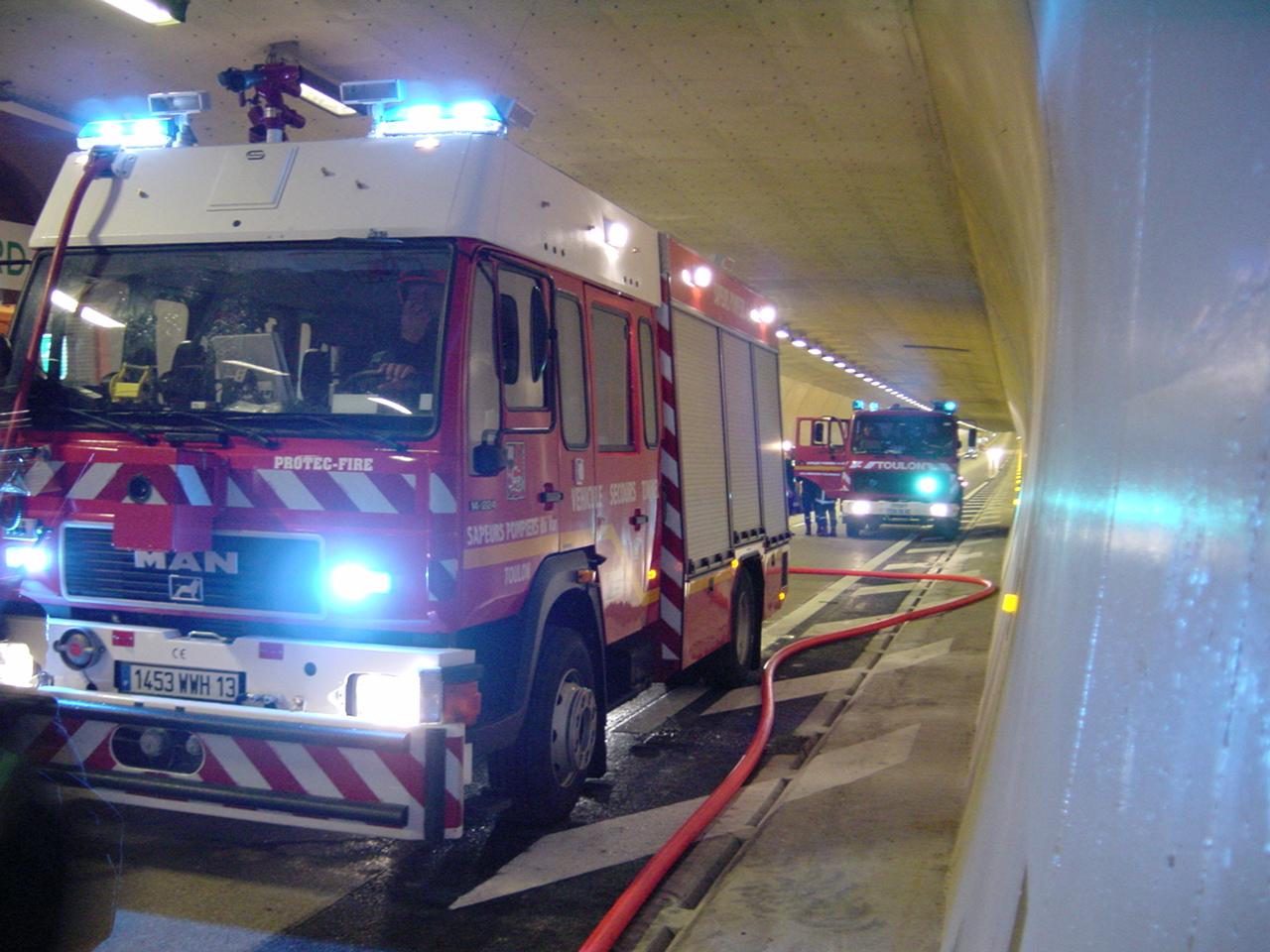
Figure1: Fire service intervention following a tunnel fire
This equipment includes:
A tunnel is an enclosed structure that usually does not permit the natural transmission of radio waves to travel very far into the tunnel. To ensure that the emergency services and maintenance personnel can remain in radio contact with their colleagues outside the tunnel, it is necessary to install equipment that will provide this service.
Multiple frequencies can be retransmitted into the tunnel by taking “off-air” radio signals and re-transmitting them into the tunnel to allow:
There are a very large number of services whose frequencies can be retransmitted into the tunnel. However, not all of them are retransmitted, due to cost and feasibility issues. As a general rule, most frequencies used by the rescue services, frequencies used by the operator, a few FM and or DAB frequencies and frequencies of cell phone operators are generally retransmitted.
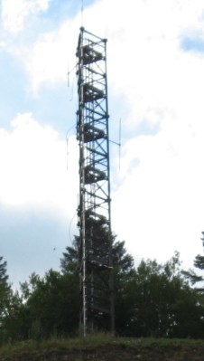
Fig 1: Outside antenna to receive radio stations “off-air”
There is usually no mandatory requirement to provide mobile telephone coverage inside tunnels. However, since the majority of tunnel users have mobile phones, it is believed to be a safer option to facilitate mobile coverage, encouraging stranded motorists to use their mobiles from inside their vehicles rather than getting out of their vehicles and using the roadside emergency telephones. Tunnel owners therefore often provide the mobile phone operators with facilities inside the technical rooms to allow them to install equipment that will provide continuing mobile phone coverage inside the tunnel.
See page on Radio break-in systems including Voice Break-In facilities, for further information.
The purpose of ventilation in a road tunnel is to provide adequate fresh air and in the event of a fire, to control smoke.
Fresh air is provided through entirely automated systems, based on information from various sensors located throughout the tunnel (opacimeters, CO sensors, NOx sensors…).
For smoke extraction, the nature of the tunnel and in particular its level of surveillance (presence or not of a manned control centre 24/7), will dictate how the ventilation is controlled:
Each panel can activate smoke extraction, or stop it if required. In certain cases (reversible longitudinal ventilation system), the panels can also control the direction in which the smoke is blown.
If a smoke control panel is located at each portal, it is important to define which panel has priority over the other (for example, when the first panel is activated, it over-rides the second), in order to avoid contradictory commands if fire officers are located at both portals.
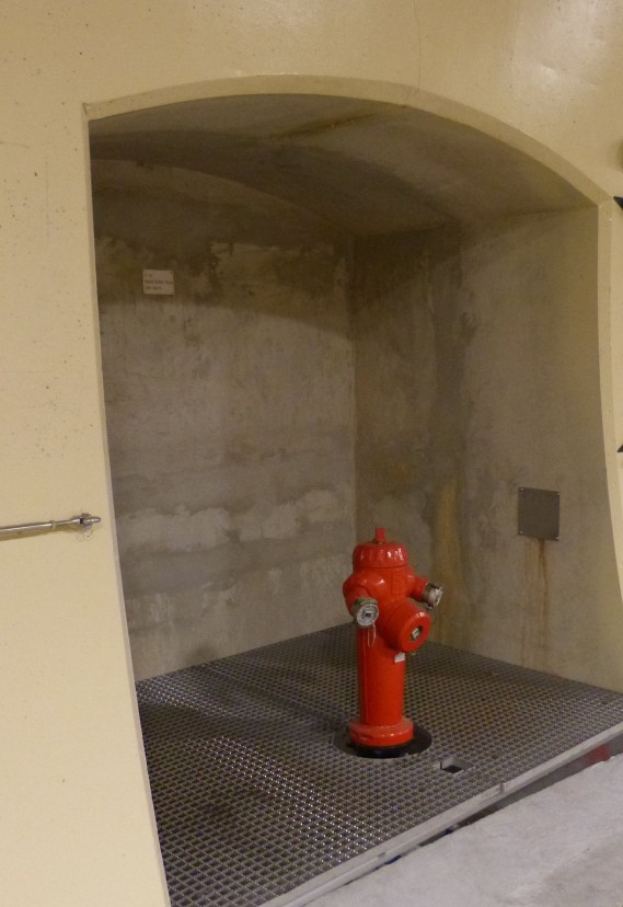
Fig 1: Fire hydrant
Hose valves are required within the road tunnel to provide a point of connection for the Fire Brigade to attach fire hoses and gain access to the water supply. Hydrants should be installed at regular intervals within the tunnel (see Section 6.3.3 "Water supply" of report 05.05.B 1999). The hydrant connections must be compatible with the responding local fire brigade(s).
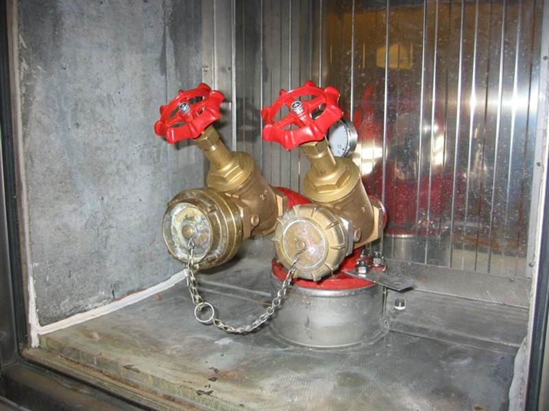
Fig 2. Fire hose valves