
In normal operating mode, the monitoring of a tunnel usually consists of a visual monitoring of traffic by means of video surveillance cameras (CCTV).
In the event of an incident in the tunnel, the alarm can be raised by video surveillance or by more specific means such as:
The ‘’quality” of the information provided by each of these devices is linked to the very nature of the device (an emergency call station makes it possible to locate and establish contact with users, whereas notification of the removal of a fire extinguisher may indicate the start of a fire, but does not provide more detailed information).
These devices therefore do not provide the operator with the same degree or ‘’quality” of information, although they provide an initial alert. The operator may use additional equipment to verify the alert or to obtain further information.
A traffic surveillance system is often installed when the level of traffic is very dense in a tunnel. Usually, a video-surveillance system is used, supplemented sometimes with counting devices. A video-surveillance installation provides the operator with important information in order to make decisions about controlling the traffic conditions in the tunnel in real time. In case of degraded or emergency operation, it allows the concerned incident zone to be viewed so that required actions may be rapidly evaluated.
Video-surveillance is thus a very valuable tool for the operator because it enables continuous incident monitoring inside the tunnel and rapid reactions when necessary.
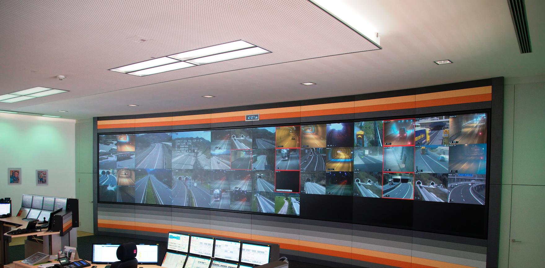
Figure 1: Example of a tunnel CCTV system
However, in order to make full use of a video-surveillance installation, it is essential to maintain a human presence, if possible continuously, at the control-command centre.
Video-surveillance is generally quite simple in its design. Cameras placed at regular intervals in the tunnel provide a complete coverage of the tunnel and its surroundings. The images are then grouped and transmitted to the control-command centre of the tunnel by networks that may or may not be dedicated to this function. The images are then received and viewed on the displays (Fig. 1).
CCTV systems can also be relayed to automatic incident detection systems (to detect smoke, fire, accidents, traffic jams or intrusions for example). AID systems are especially useful for long tunnels, where it is difficult for the operator to observe the entire tunnel even with a wall of screens.
E
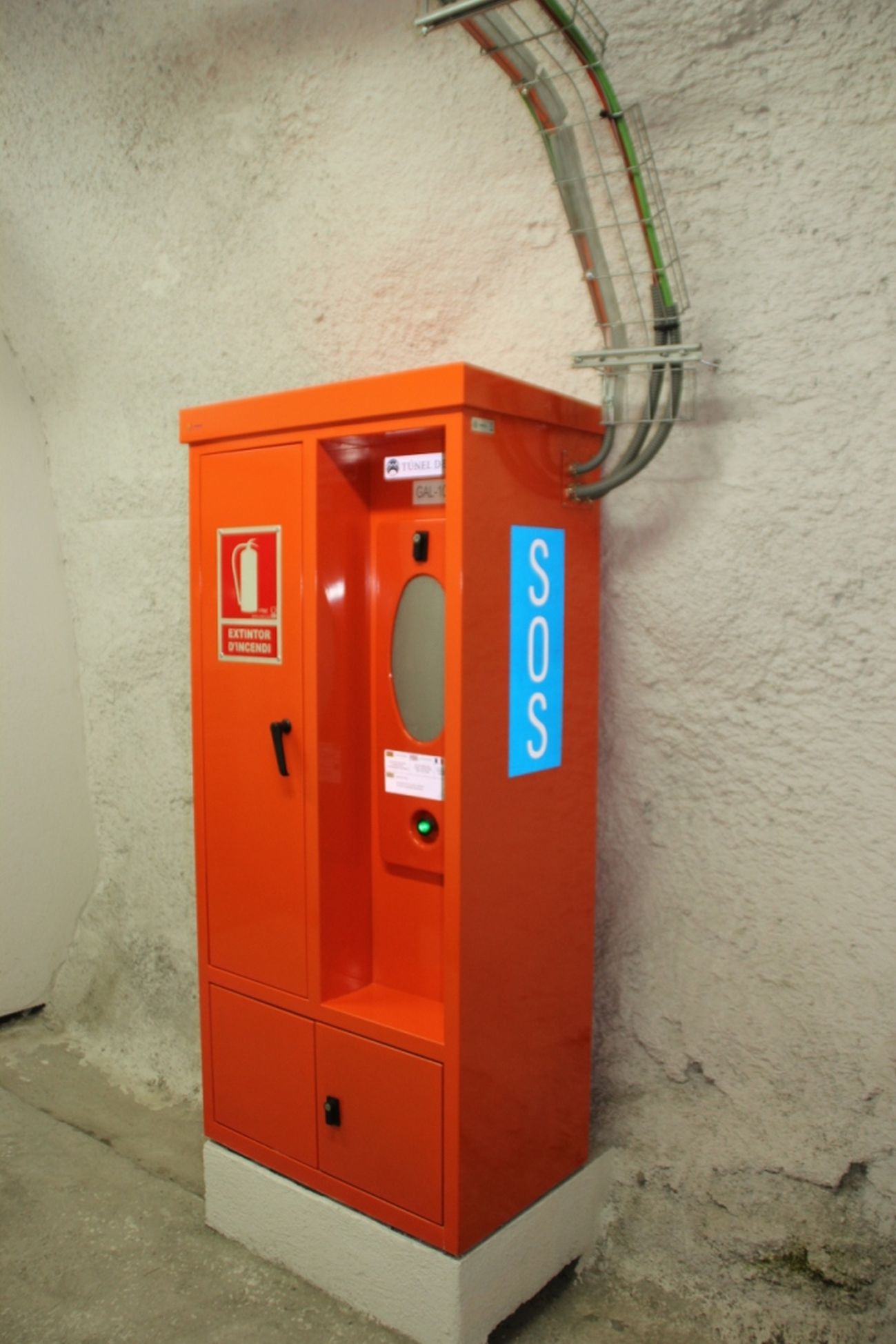
Figure 1: Emergency telephone in a road tunnel (Spain)
Each emergency telephone is given a unique numeral ID which is displayed onscreen when the user/victim picks up the receiver, which allows the control-centre personnel to quickly locate the source of the call. Likewise, the control-command centre can also ring the emergency telephone and provide the user/victim with advisory instructions.
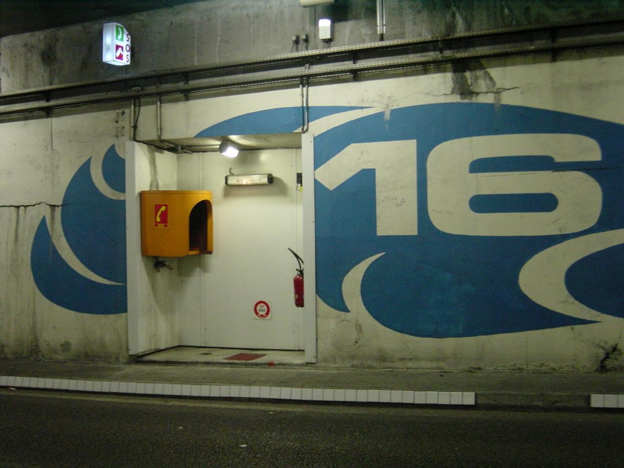
Figure 2: Emergency telephone in a safety recess (France)
These emergency telephones are installed at fixed intervals on boxes or in emergency stations of different types. The distance between two emergency telephones is often specified by regulations and therefore varies from one country to another.
The structure of this device is quite simple. The emergency telephones in the tunnel are connected to a centre that receives the calls made from the tunnel. Usually, this centre is located in the control-command centre of the tunnel and sometimes in the premises of police services under whose jurisdiction the tunnel is placed.
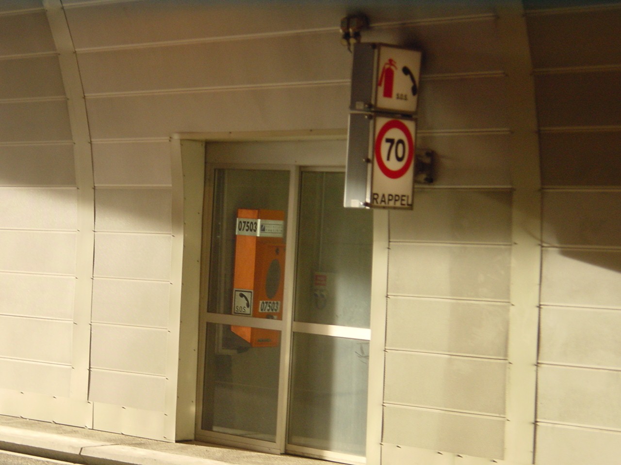
Figure 3: Emergency telephone in an emergency station (France)
As mentioned above, the user has access to several devices for use in a tunnel, particularly in emergencies. These devices include fire extinguishers, emergency stations (containing emergency telephones and fire extinguishers) and emergency exit doors.
Automatic alarms are triggered when emergency systems such as doors and/or extinguishers are used. For fire extinguishers, it is the action of removing the equipment from its support that triggers the alarm. For emergency station and emergency exit doors, it is the opening of the door or the detection of a presence in the exit that is the trigger.
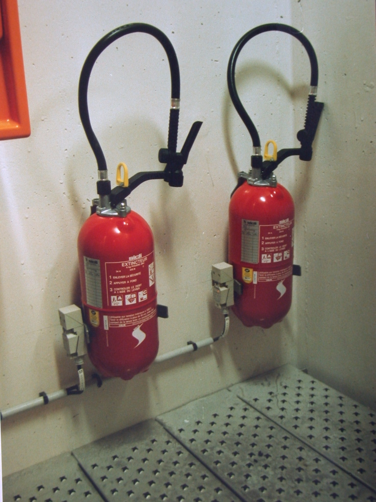
Fig 1 : Extinguishers with sensors at the
The opening of a door or removal of an extinguisher will often result in automated actions being triggered. For instance, a CCTV camera may be programmed to automatically turn to the door that was opened to aid a more efficient response by the operator. It is essential for the tunnel operator to be informed as early as possible when a user operates one of these devices, in order to take adequate actions. Where national standards require the tunnel to be monitored by full time Operators, then these devices will be monitored using switches. These switches are connected to the plant monitoring SCADA system. In the event that a door is opened, or an extinguisher removed, then the plant monitoring system will raise an alarm to the operator located in the control room.
Manual call points (also named Alarm pushbuttons) allow a user to send an alarm to the control-command centre in case of an incident in a tunnel. These manual call points are not very expensive so they can be installed at frequent intervals, typically every 25m to 50m.
These devices are not often activated by tunnel users because users tend to prefer using emergency call stations (emergency telephones) that provide real-time audio conversations with an operator. Manual call points do not provide real-time feed back to the user.
Most road tunnels that have a manned control room are equipped with a Closed-Circuit TV (CCTV) system (refer to the page on CCTV system).The CCTV images are usually displayed on a video wall in the control centre. The CCTV system allows operators to monitor the tunnel to identify incidents. It can often be difficult for the operator to monitor more than a few displays simultaneously because of the large quantity of images available and with other duties that the operator has to perform.
To ensure that incidents, such as slow moving or stationary traffic, are detected early, tunnel operators are increasingly installing Automatic Incident Detection (AID) systems. In some countries, the use of such equipment is mandatory for certain types of tunnels.
Two main types of AID systems are available for use in road tunnels, Video-based and Radar based. The video-based systems (V-AID) generally use fixed CCTV cameras to provide full coverage of the roads and walkways. The video-based system provides useful time-stamped video images of incidents which can help in assessing why incidents occurred and who or what may be responsible for causing the incident. Fixed camera V-AID systems are also available with Infrared cameras so that the system can provide video images in low light and smoke-filled conditions. Radar based systems cover a greater area than one fixed camera, so require less infrastructure in the tunnel. The output from a radar system is a grey-scale image that works in all environmental conditions in a tunnel.
V-AID systems are normally based on computer-based analysis of video image streams generated from cameras set up to view tunnel traffic. The video analysis compares each frame from the video camera with the previous frame and checks for differences outside what is considered to be ‘normal’ behaviour. A number of algorithms are available from the VAID system which can detect a range of incidents, including:
Each type of event to be detected is associated with a false alarm frequency. Increasing the number of events to detect will therefore increase the occurrence of false alarms and thus reduce the reliability of the AID system.
It is therefore very important to limit the type of events to be detected to those that are strictly necessary in order to make the system as reliable as possible, to limit the frequency of false alarms and to reduce the cases of non-detection of events.
Since serious vehicle fires normally develop after traffic has stopped (e.g. following an accident), it follows that a 'stopped vehicle' alarm from an AID system can be expected to precede alarms triggered by other systems, such as temperature and smoke detectors. This early warning provided by AID systems provides time for tunnel operators to confirm the nature and location of the incident, and to allow more effective intervention. This may be through the choice of optimal ventilation configuration, prevention of secondary accidents through operational measures, rapid warning to motorists upstream of the incident, and tunnel closure. It also gives operators the opportunity to call the emergency services, display warning or information messages on variable message signs, broadcast messages on public address and the radio voice break-in systems, call to breakdown lorries, advice to exit the tunnel, etc.
Video smoke detection systems are described in Section 6.3.3 "Currently Used Methods" of report 05.16.B 2006.
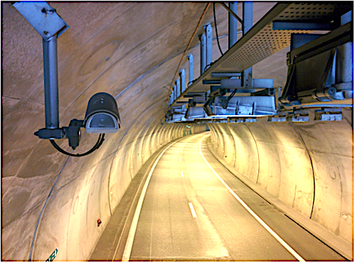
Fig. 1: Camera equipped with AID (photo Credit CETU)
Video-based AID systems can also provide real-time information on the traffic flow, volume and speed. They can record pictures at the origin of the incident (Fig. 1) and can interact with other systems such as the Supervisory Control and Data Acquisition (SCADA) system. Video-based AID systems normally include IP (Internet Protocol) cameras, a video image processing system processing images from one or several cameras. The video images may be fed back to monitors or computer displays in the control centre. The V-AID cameras may also be monitored by the video management system, comprising of redundant servers, providing video and other functions (mass recording of video and incidents from the AID system, collecting and storing real-time traffic data and traffic events, interfacing with the tunnel SCADA system), network equipment and communications lines (optical fibres, coaxial and Unshielded Twisted Pair cables).
Recent technology in video processing allows the V-AID algorithms to be run on the cameras (or near the cameras), rather than on a central server. This approach means that only video incident files of detected incidents are transmitted to the SCADA system when there is an incident, rather than constantly transmitting (streaming) real time video from all cameras. This reduces the transmission load on the tunnel communications network
The design of AID systems in tunnels should be undertaken with due account of the following issues:
The 2009 Routes/Roads article "Fire Detection Systems in Road Tunnels - Lessons Learnt from the International Research Project"concluded that "to deal with obstructions, most sensor manufacturers recommend two sensors covering the same area from different angles, such as from both directions within a tunnel". Multiple cameras may also be required for redundancy purposes, in case of camera failure. Typically, the camera fields of view are designed to overlap, such that failure of any one camera can be compensated through the images from neighbouring cameras.
Section IV.2.1. "Incident Detection Devices" of report 05.15.B 2004 suggests that camera locations can vary from 30 to 150 meters if they are used for automatic incident detection. More recent recommendations from the V-AID manufacturers is that the cameras should cover a distance of no more than twenty times its mounting height. Therefore, if a camera is mounted at 5 m above the road then it should be able to provide reasonably accurate detection of incidents for a distance of 100m. However, as mentioned above, to ensure redundancy coverage in the event of a camera failure, then V-AID cameras should be installed every 50 to 80 m.
The performance of an AID system depends to a great extent on successful commissioning and calibration prior to deployment. Experience shows that the decision on detection time for the system has an important influence on the systems detection accuracy and the amount of false alarms registered. Experience from existing tunnel installations indicates that such commissioning and calibration can take several months under operation to undertake.
Fire and smoke detectors are always an integral part of a control loop which comprises sensors, alarm triggering equipment, transmission cabling, evaluation units, etc., and which together are generally referred to as a fire alarm system.
Fire and smoke alarm systems in road tunnels are designed to detect fires and smoke production as fast as possible so that safety equipment and procedures can be activated without delay. Their main objectives should be to:
Fire detection principles are based on perceived parameters i.e. heat, smoke, radiation and production of typical chemical substances. Therefore, fire detection sensors include:
Each of these detectors has their own specific application domain, related to its response time, robustness, reliability, etc.
Recently video AID systems have proven to be very efficient and fast in detecting fires. They detect incidents and any object or vehicle which does not conform to the normal expected traffic stream. The cameras can be automatically turned towards the incident scene, which enables the operator to discover the very early start of a fire.
Fire/smoke detection systems are described in Section 6.3 "Fire detection" of the report 2006 05.16.B.
Generally speaking, fire detectors in road tunnels must be designed to withstand the following environmental conditions: air velocities up to 10 m/s, reduced visibility resulting from diesel exhaust fumes and abrasive wear stemming from tires and the road surface, increased and short-term fluctuating concentrations of pollutants (carbon monoxide (CO), carbon dioxide (CO2), nitrogen oxides and hydrocarbons), changing headlight intensities, engine heat and hot fumes, vehicle exhaust gases, electromagnetic interferences, mixed vehicular traffic (i.e., cars, small lorries, heavy load lorries, buses and tankers) that will result in varying degrees of tunnel cross section obstruction.
It cannot be stressed enough that they must have a high degree of fail-safe operation and be able to determine the location of the fire as precisely as possible. It is advisable that fire detection systems possess a certain level of intelligence in order to avoid false alarms, as to rectify them could entail significant expenses and even worse, may eventually discourage the operators from paying attention to the alarms.
Furthermore, it is imperative that the fire detection/alarm installation is reasonably priced, has low operating costs and is simple to maintain: refer Section 6.3 "Fire detection" of the report 2006 05.16.B.
The following parameters for automatic fire detectors are specified in national and international codes and standards : maximum time for a fire to be detected, determination of the fire location, minimum fire load to be detected, approved detection methods, assembly points for fire alarms, details pertaining to which tunnels should be provided with automatic fire alarm installations (e.g. length of tunnel, tunnels with mechanical ventilation, tunnels that are not permanently monitored by personnel, short tunnels with particularly high traffic densities).
A list of detailed reference material regarding fire detector parameters are described in codes and can be found in Section 10 "References" of the report 2006 05.16.B.
The efficiency of fire detection is not only based on the type of devices (temperature, light beam extinction, ionisation, etc.), but also on the detection strategy which has been developed, which includes the number of sensors and their level of surveillance in the tunnel.
Automatic incident detection, analysis of video images including AID systems, closed-circuit television (CCTV) observation, equipment such as fire extinguishers which activate alarms by the removal, as well as the emergency telephones are generally good means to raise an alarm.
Many detectors in use are based on heat and on the rate of temperature rise. When well calibrated, this type of system generates only few false alarms, but may have a slow reaction rate. Detectors based on smoke obscuration give early signals but suffer more false alarms because of smoke exhaust from diesel vehicles: refer to Section VI.3.1 "Fire detection" of report 05.05.B 1999.
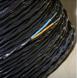
Figure 1: Linear temperature sensor